Information injection-pump assembly
BOSCH
9 400 617 952
9400617952
ZEXEL
106861-0813
1068610813
NISSAN-DIESEL
1671397572
1671397572

Rating:
Service parts 106861-0813 INJECTION-PUMP ASSEMBLY:
1.
_
7.
COUPLING PLATE
8.
_
9.
_
11.
Nozzle and Holder
1660097015
12.
Open Pre:MPa(Kqf/cm2)
19.6(200)

15.
NOZZLE SET
Include in #1:
106861-0813
as INJECTION-PUMP ASSEMBLY
Cross reference number
BOSCH
9 400 617 952
9400617952
ZEXEL
106861-0813
1068610813
NISSAN-DIESEL
1671397572
1671397572
Zexel num
Bosch num
Firm num
Name
106861-0813
9 400 617 952
1671397572 NISSAN-DIESEL
INJECTION-PUMP ASSEMBLY
RD8 * K
RD8 * K
Calibration Data:
Adjustment conditions
Test oil
1404 Test oil ISO4113 or {SAEJ967d}
1404 Test oil ISO4113 or {SAEJ967d}
Test oil temperature
degC
40
40
45
Nozzle and nozzle holder
105780-8140
Bosch type code
EF8511/9A
Nozzle
105780-0000
Bosch type code
DN12SD12T
Nozzle holder
105780-2080
Bosch type code
EF8511/9
Opening pressure
MPa
17.2
Opening pressure
kgf/cm2
175
Injection pipe
Outer diameter - inner diameter - length (mm) mm 8-3-600
Outer diameter - inner diameter - length (mm) mm 8-3-600
Overflow valve
132424-0620
Overflow valve opening pressure
kPa
157
123
191
Overflow valve opening pressure
kgf/cm2
1.6
1.25
1.95
Tester oil delivery pressure
kPa
157
157
157
Tester oil delivery pressure
kgf/cm2
1.6
1.6
1.6
Direction of rotation (viewed from drive side)
Right R
Right R
Injection timing adjustment
Direction of rotation (viewed from drive side)
Right R
Right R
Injection order
1-8-7-5-
4-3-6-2
Pre-stroke
mm
3.65
3.6
3.7
Beginning of injection position
Governor side NO.1
Governor side NO.1
Difference between angles 1
Cal 1-8 deg. 45 44.5 45.5
Cal 1-8 deg. 45 44.5 45.5
Difference between angles 2
Cal 1-7 deg. 90 89.5 90.5
Cal 1-7 deg. 90 89.5 90.5
Difference between angles 3
Cal 1-5 deg. 135 134.5 135.5
Cal 1-5 deg. 135 134.5 135.5
Difference between angles 4
Cal 1-4 deg. 180 179.5 180.5
Cal 1-4 deg. 180 179.5 180.5
Difference between angles 5
Cal 1-3 deg. 225 224.5 225.5
Cal 1-3 deg. 225 224.5 225.5
Difference between angles 6
Cal 1-6 deg. 270 269.5 270.5
Cal 1-6 deg. 270 269.5 270.5
Difference between angles 7
Cyl.1-2 deg. 315 314.5 315.5
Cyl.1-2 deg. 315 314.5 315.5
Injection quantity adjustment
Adjusting point
A
Rack position
11.6
Pump speed
r/min
700
700
700
Average injection quantity
mm3/st.
105.1
104.1
106.1
Max. variation between cylinders
%
0
-4
4
Basic
*
Fixing the lever
*
Injection quantity adjustment_02
Adjusting point
B
Rack position
6.9+-0.5
Pump speed
r/min
250
250
250
Average injection quantity
mm3/st.
13.1
11.1
15.1
Max. variation between cylinders
%
0
-10
10
Fixing the rack
*
Timer adjustment
Pump speed
r/min
650--
Advance angle
deg.
0
0
0
Remarks
Start
Start
Timer adjustment_02
Pump speed
r/min
600
Advance angle
deg.
0.5
Timer adjustment_03
Pump speed
r/min
1150
Advance angle
deg.
3
2.5
3.5
Timer adjustment_04
Pump speed
r/min
-
Advance angle
deg.
4
4
4
Remarks
Measure the actual speed, stop
Measure the actual speed, stop
Test data Ex:
Governor adjustment
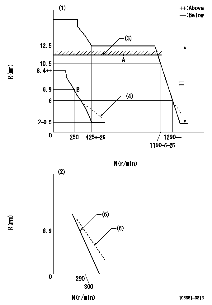
N:Pump speed
R:Rack position (mm)
(1)Adjust with speed control lever at full position (minimum-maximum speed specification)
(2)Adjust with the load control lever in the full position (variable speed specification).
(3)Rack limit using the stop lever: R1
(4)Damper spring setting: DL
(5)Main spring setting
(6)Set idle sub-spring
----------
R1=11.6mm DL=5.6-0.2mm
----------
----------
R1=11.6mm DL=5.6-0.2mm
----------
Speed control lever angle
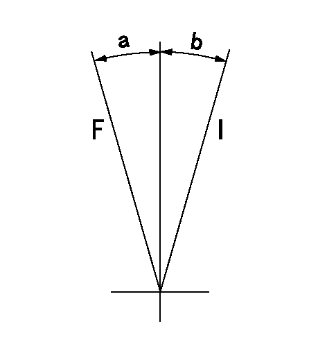
F:Full speed
I:Idle
----------
----------
a=10deg+-5deg b=10deg+-5deg
----------
----------
a=10deg+-5deg b=10deg+-5deg
0000000901
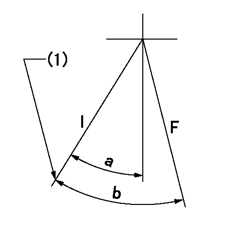
F:Full load
I:Idle
(1)Stopper bolt setting
----------
----------
a=24.5deg+-5deg b=38.5deg+-3deg
----------
----------
a=24.5deg+-5deg b=38.5deg+-3deg
Stop lever angle
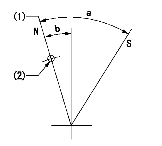
N:Pump normal
S:Stop the pump.
(1)Rack position = aa
(2)Use the hole at R = bb
----------
aa=11.6mm bb=32mm
----------
a=29.5deg+-5deg b=4deg+-5deg
----------
aa=11.6mm bb=32mm
----------
a=29.5deg+-5deg b=4deg+-5deg
Timing setting

(1)Pump vertical direction
(2)Position of the coupling's key groove at the beginning of injection of the No. 8 cylinder.
(3)-
(4)-
----------
----------
a=(90deg)
----------
----------
a=(90deg)
Information:
Caterpillar: Confidential Yellow
PSP FOR FUEL INJECTION LINE FAILURES ON 627E, 627E PP AND 637E SCRAPERS - MAILED WORLDWIDE EXCEPT BRAZIL
The information supplied in this service letter may not be valid after the termination date of this program. Do not perform the work outlined in this Service Letter after the termination date without first contacting your Caterpillar product analyst.
U-35 A-20 AU-22 E-18 O-21 1252 PS4200 This Program can be administered either before or after a failure. In either case the decision whether to apply the Program is made by the dealer. When reporting the repair, use "PS4200" as Part Number and "7755" as Group Number. Termination Date
February 28, 1989
Problem
The fuel injection lines on 627E, 627E PP and 637E Scrapers may crack as a result of excessive vibration. New fuel injection lines and supporting brackets can be installed.
Affected Product
Model Identification Number 627E 6EBl - 513 627E PP 6GB513 - 177, 579-582, 584, 585, 587, 588, 590-603 637E 1FB1 - 338, 341-348, 350-352 1JB1 - 548, 550, 553, 555, 556, 558-561, 563
Parts Needed
1 - 7C9564 Line As. 1 - 7C9565 Line As. 1 - 7C9566 Line As. 11 - 1W9168 Clamp 8 - 5P4939 Screw As. 11 - lW9169 Clamp 1 - 9Y1586 Bracket As. 1 - 9Y1653 Bracket As. 3 - 9N3388 Screw 1 - 9Y2681 Bar (as needed) The 9Y2681 Bar is only needed if the engine is not equipped with heat shields.
Action Required
Install the new parts as shown in the attached illustration. It is important that the 1W9168 and 1W9169 Clamps be installed at the locations shown in the illustration.
Service Claim Allowances
Product Caterpillar Dealer Suggested Customer Suggested smu/age Parts Labor Hrs. Parts Labor Hrs. Parts Labor Hrs. whichever (D/N) (Cost) (C/L) (Sell) comes first 0-2500
Have questions with 106861-0813?
Group cross 106861-0813 ZEXEL
Nissan-Diesel
Nissan-Diesel
106861-0813
9 400 617 952
1671397572
INJECTION-PUMP ASSEMBLY
RD8
RD8