Information injection-pump assembly
ZEXEL
106861-0530
1068610530
Rating:
Cross reference number
ZEXEL
106861-0530
1068610530
Zexel num
Bosch num
Firm num
Name
106861-0530
INJECTION-PUMP ASSEMBLY
Calibration Data:
Adjustment conditions
Test oil
1404 Test oil ISO4113 or {SAEJ967d}
1404 Test oil ISO4113 or {SAEJ967d}
Test oil temperature
degC
40
40
45
Nozzle and nozzle holder
105780-8140
Bosch type code
EF8511/9A
Nozzle
105780-0000
Bosch type code
DN12SD12T
Nozzle holder
105780-2080
Bosch type code
EF8511/9
Opening pressure
MPa
17.2
Opening pressure
kgf/cm2
175
Injection pipe
Outer diameter - inner diameter - length (mm) mm 8-3-600
Outer diameter - inner diameter - length (mm) mm 8-3-600
Overflow valve
132424-0620
Overflow valve opening pressure
kPa
157
123
191
Overflow valve opening pressure
kgf/cm2
1.6
1.25
1.95
Tester oil delivery pressure
kPa
157
157
157
Tester oil delivery pressure
kgf/cm2
1.6
1.6
1.6
Direction of rotation (viewed from drive side)
Right R
Right R
Injection timing adjustment
Direction of rotation (viewed from drive side)
Right R
Right R
Injection order
1-8-7-5-
4-3-6-2
Pre-stroke
mm
3.65
3.6
3.7
Beginning of injection position
Governor side NO.1
Governor side NO.1
Difference between angles 1
Cal 1-8 deg. 45 44.5 45.5
Cal 1-8 deg. 45 44.5 45.5
Difference between angles 2
Cal 1-7 deg. 90 89.5 90.5
Cal 1-7 deg. 90 89.5 90.5
Difference between angles 3
Cal 1-5 deg. 135 134.5 135.5
Cal 1-5 deg. 135 134.5 135.5
Difference between angles 4
Cal 1-4 deg. 180 179.5 180.5
Cal 1-4 deg. 180 179.5 180.5
Difference between angles 5
Cal 1-3 deg. 225 224.5 225.5
Cal 1-3 deg. 225 224.5 225.5
Difference between angles 6
Cal 1-6 deg. 270 269.5 270.5
Cal 1-6 deg. 270 269.5 270.5
Difference between angles 7
Cyl.1-2 deg. 315 314.5 315.5
Cyl.1-2 deg. 315 314.5 315.5
Injection quantity adjustment
Adjusting point
A
Rack position
11.8
Pump speed
r/min
700
700
700
Average injection quantity
mm3/st.
107
107
109
Max. variation between cylinders
%
0
-4
4
Basic
*
Fixing the lever
*
Injection quantity adjustment_02
Adjusting point
B
Rack position
11.8
Pump speed
r/min
1100
1100
1100
Average injection quantity
mm3/st.
110
106
114
Max. variation between cylinders
%
0
-4
4
Fixing the lever
*
Injection quantity adjustment_03
Adjusting point
C
Rack position
6.2+-0.5
Pump speed
r/min
235
235
235
Average injection quantity
mm3/st.
18.5
16.6
20.4
Max. variation between cylinders
%
0
-10
10
Fixing the rack
*
Timer adjustment
Pump speed
r/min
300+100
Advance angle
deg.
0
0
0
Remarks
Start
Start
Timer adjustment_02
Pump speed
r/min
700
Advance angle
deg.
1.7
1.2
2.2
Timer adjustment_03
Pump speed
r/min
1000
Advance angle
deg.
3.5
3
4
Timer adjustment_04
Pump speed
r/min
1250+50
Advance angle
deg.
5.5
5
6
Remarks
Finish
Finish
Test data Ex:
Governor adjustment
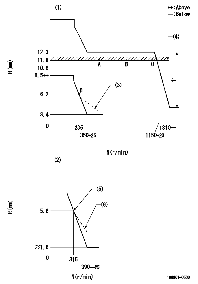
N:Pump speed
R:Rack position (mm)
(1)Adjust with speed control lever at full position (minimum-maximum speed specification)
(2)Adjust with the load control lever in the full position (variable speed specification).
(3)Damper spring setting: DL
(4)Rack limit using stop lever
(5)Main spring setting
(6)Idle sub spring setting: L1.
----------
DL=5.6-0.2mm L1=5.6-0.2mm
----------
----------
DL=5.6-0.2mm L1=5.6-0.2mm
----------
Speed control lever angle
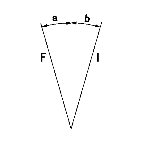
F:Full speed
I:Idle
----------
----------
a=10.5deg+-5deg b=10deg+-5deg
----------
----------
a=10.5deg+-5deg b=10deg+-5deg
0000000901
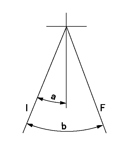
F:Full load
I:Idle
----------
----------
a=21.5deg+-5deg b=34deg+-3deg
----------
----------
a=21.5deg+-5deg b=34deg+-3deg
Stop lever angle
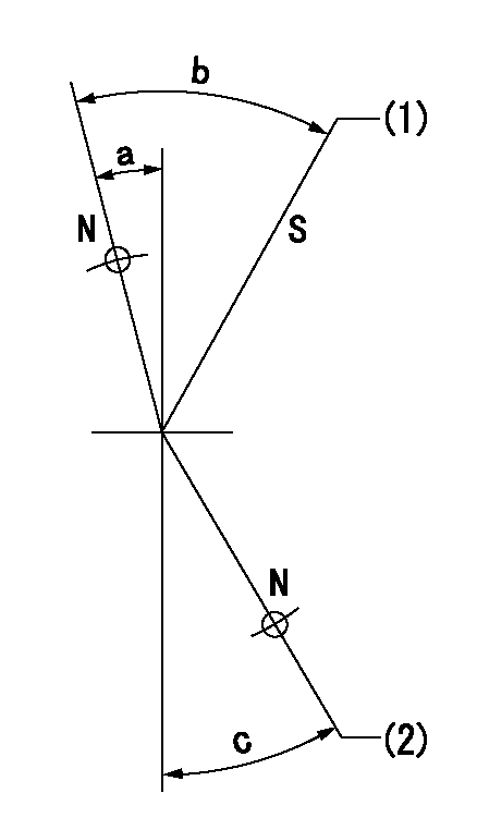
N:Pump normal
S:Stop the pump.
(1)Set rack position = aa
(2)Set the rack position at bb
----------
aa=1+0.5mm bb=11.8mm
----------
a=5.5deg+-5deg b=32deg+-3deg c=29deg+-5deg
----------
aa=1+0.5mm bb=11.8mm
----------
a=5.5deg+-5deg b=32deg+-3deg c=29deg+-5deg
Information:
Introduction
1. Type 2 fuel injector. 2. Two piece follower. 3. Nose cone. 4. Nozzle assembly.Tools are now available for the removal and installation of nose cone (3), on type 2 fuel injectors (1), when it is necessary to replace a nozzle assembly (4). Type 2 fuel injectors can be identified by the two piece follower (2).
5. 1U9395 Plate. 6. 1U8701 Socket.Use 1U9395 Plate (5) with the 6V4830 Fixture Group (not shown) and the procedure given in this instruction, for the removal and installation of nozzle assembly (4).Earlier type 2 injectors have a nose cone that has serrations on its exterior. These serrations will be damaged when the nose cone is removed. A damaged nose cone is not to be used again. A 7C9795 Nose Cone is available for use as a replacement for the original nose cone.The 7C9795 Nose Cone has a hexagon shape on its exterior. This nose cone can be installed and tightened using 1U8701 Socket (6). When the 7C9795 Nose Cone is installed, be sure to tighten it according to the procedure given in this instruction.Removal and Installation of Nose Cone and Nozzle Assembly
1. Remove the original plate from the 6V4830 Fixture Group and install 1U9395 Plate (1).2. Put injector (2) in position on the fixture group. If the exterior of the injector nose cone is a hexagon shape as shown at location (A), use the 1U8701 Socket for nose cone removal. 3. If the exterior of the nose cone has serrations as shown at location (B), use a pipe wrench, as shown, to remove the nose cone. Anytime a pipe wrench is used to remove a nose cone, the nose cone will be damaged. Never use or install a damaged nose cone on an injector. Always install a new 7C9795 Nose Cone as a replacement. 4. After the nose cone has been loosened, use a hammer and 6V4822 Tip Driver (3) to tap the nozzle assembly as shown. This is done to break the connection between the nozzle assembly and the nose cone. Be sure to use only the 6V4822 Tip Driver in this procedure, because use of a standard punch, or any other similar tool will cause damage to the nozzle tip.5. Remove the nose cone and nozzle assembly. 6. Inspect surface (C) in the injector. This is the sealing surface for the nozzle assembly. This surface must be clean and free of any scratches, nicks or burrs. Even a piece of lint from a shop towel can cause a leak and destroy nozzle performance. 7. Remove original O-ring seal (4). Install a new O-ring seal, refer to the Parts Book for the correct part number. Make sure the O-ring seal is not damaged during installation.Use a generous amount of 1P0808 Grease, or a good grade of multi-purpose lubricant, to lubricate the O-ring seal before the nose cone is installed.8. Install new nozzle assembly (5) on the injector. 9. Install and finger tighten the new 7C9795 Nose Cone on the injector. Using a
Have questions with 106861-0530?
Group cross 106861-0530 ZEXEL
Nissan-Diesel
Nissan-Diesel
106861-0530
INJECTION-PUMP ASSEMBLY