Information injection-pump assembly
ZEXEL
106861-0160
1068610160

Rating:
Service parts 106861-0160 INJECTION-PUMP ASSEMBLY:
1.
_
6.
COUPLING PLATE
7.
COUPLING PLATE
8.
_
9.
_
11.
Nozzle and Holder
16600-97012
12.
Open Pre:MPa(Kqf/cm2)
19.6{200}
15.
NOZZLE SET
Include in #1:
106861-0160
as INJECTION-PUMP ASSEMBLY
Cross reference number
ZEXEL
106861-0160
1068610160
Zexel num
Bosch num
Firm num
Name
106861-0160
INJECTION-PUMP ASSEMBLY
14CD PE8P PE
14CD PE8P PE
Calibration Data:
Adjustment conditions
Test oil
1404 Test oil ISO4113 or {SAEJ967d}
1404 Test oil ISO4113 or {SAEJ967d}
Test oil temperature
degC
40
40
45
Nozzle and nozzle holder
105780-8140
Bosch type code
EF8511/9A
Nozzle
105780-0000
Bosch type code
DN12SD12T
Nozzle holder
105780-2080
Bosch type code
EF8511/9
Opening pressure
MPa
17.2
Opening pressure
kgf/cm2
175
Injection pipe
Outer diameter - inner diameter - length (mm) mm 8-3-600
Outer diameter - inner diameter - length (mm) mm 8-3-600
Tester oil delivery pressure
kPa
157
157
157
Tester oil delivery pressure
kgf/cm2
1.6
1.6
1.6
Direction of rotation (viewed from drive side)
Right R
Right R
Injection timing adjustment
Direction of rotation (viewed from drive side)
Right R
Right R
Injection order
1-8-7-5-
4-3-6-2
Pre-stroke
mm
3.65
3.6
3.7
Beginning of injection position
Governor side NO.1
Governor side NO.1
Difference between angles 1
Cal 1-8 deg. 45 44.5 45.5
Cal 1-8 deg. 45 44.5 45.5
Difference between angles 2
Cal 1-7 deg. 90 89.5 90.5
Cal 1-7 deg. 90 89.5 90.5
Difference between angles 3
Cal 1-5 deg. 135 134.5 135.5
Cal 1-5 deg. 135 134.5 135.5
Difference between angles 4
Cal 1-4 deg. 180 179.5 180.5
Cal 1-4 deg. 180 179.5 180.5
Difference between angles 5
Cal 1-3 deg. 225 224.5 225.5
Cal 1-3 deg. 225 224.5 225.5
Difference between angles 6
Cal 1-6 deg. 270 269.5 270.5
Cal 1-6 deg. 270 269.5 270.5
Difference between angles 7
Cyl.1-2 deg. 315 314.5 315.5
Cyl.1-2 deg. 315 314.5 315.5
Injection quantity adjustment
Adjusting point
A
Rack position
9.8
Pump speed
r/min
700
700
700
Average injection quantity
mm3/st.
113.8
112.8
114.8
Max. variation between cylinders
%
0
-4
4
Basic
*
Fixing the lever
*
Injection quantity adjustment_02
Adjusting point
B
Rack position
9.8
Pump speed
r/min
1000
1000
1000
Average injection quantity
mm3/st.
116
113
119
Max. variation between cylinders
%
0
-4
4
Fixing the lever
*
Injection quantity adjustment_03
Adjusting point
C
Rack position
9.8
Pump speed
r/min
1200
1200
1200
Average injection quantity
mm3/st.
120.6
116.6
124.6
Max. variation between cylinders
%
0
-4
4
Fixing the lever
*
Injection quantity adjustment_04
Adjusting point
D
Rack position
6.9+-0.5
Pump speed
r/min
205
205
205
Average injection quantity
mm3/st.
18.5
16.6
20.4
Max. variation between cylinders
%
0
-10
10
Fixing the rack
*
Injection quantity adjustment_05
Adjusting point
E
Rack position
10.4+-0.
5
Pump speed
r/min
300
300
300
Average injection quantity
mm3/st.
104
102
106
Fixing the lever
*
Timer adjustment
Pump speed
r/min
300+100
Advance angle
deg.
0
0
0
Remarks
Start
Start
Timer adjustment_02
Pump speed
r/min
700
Advance angle
deg.
3
2.5
3.5
Timer adjustment_03
Pump speed
r/min
1000
Advance angle
deg.
5.6
5.1
6.1
Timer adjustment_04
Pump speed
r/min
1250+50
Advance angle
deg.
8
7.5
8.5
Remarks
Finish
Finish
Test data Ex:
Governor adjustment
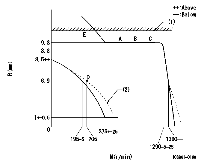
N:Pump speed
R:Rack position (mm)
(1)RACK LIMIT: RAL
(2)Adjust the damper spring so that pump speed is N1 and rack position is R1.
----------
RAL=(10.4+0.2)mm N1=200r/min R1=6.9mm
----------
----------
RAL=(10.4+0.2)mm N1=200r/min R1=6.9mm
----------
0000000901
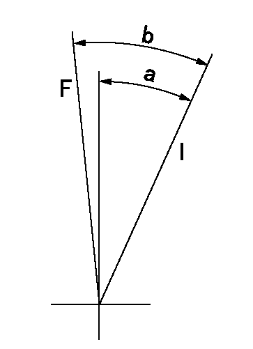
F:Full load
I:Idle
----------
----------
a=(15deg) b=17deg+-2deg
----------
----------
a=(15deg) b=17deg+-2deg
Stop lever angle
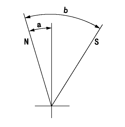
N:Normal
S:Stop the pump.
----------
----------
a=8.3deg b=(30.5deg)
----------
----------
a=8.3deg b=(30.5deg)
0000001501 MICRO SWITCH
Switch adjustment
Adjust the bolt so that the lower lever position is obtained when the switch is turned ON.
(1)Speed N1
(2)Rack position Ra
----------
N1=300r/min Ra=5.5mm
----------
----------
N1=300r/min Ra=5.5mm
----------
Information:
Core Management
Please refer to the Caterpillar® Core Management Information System (CMIS 2) Parts Information application describing all reman part/CAF and related information. Also refer to other CMIS 2 inquiry applications such as Customer Profiles, Inspection Reason Codes, Inspection Line Inquiry, Add Charge Information, Entitlement Activity, Entitlement Inquiry, CCR Inquiry, CCR Entry, Shipment Processing; Process Packaging Grief; and Reporting to properly manage core returns and monitor inspection performance. This information will be available to all dealers worldwide after your CMIS 2 conversion date. In the meantime, please continue to use the current CMIS Entitlement Parts Inquiry Screen describing the list of parts in a Core Acceptability Family (CAF) and related part number detail.
For the latest updates of Reman Policies and Core Management (SELD0122), Core Management Systems & Operations Procedures (SELD0040), and Shipping Instructions (SELD0039), go to the Reman Dealer website https://reman.cat.com
If you have any questions regarding core return processing, feel free to call Corinth toll free at (800) 537-2928. For assistance with technical questions, call the Peoria Reman Customer Satisfaction Hot Line also toll free at (888) 88-REMAN or use our E-mail address--Reman_Help.
RWSmith
Remanufactured Products Group
LC-2148 (309) 675-5445
Have questions with 106861-0160?
Group cross 106861-0160 ZEXEL
Nissan-Diesel
106861-0160
INJECTION-PUMP ASSEMBLY