Information injection-pump assembly
BOSCH
9 400 612 051
9400612051
ZEXEL
106693-6270
1066936270
ISUZU
8943920570
8943920570
Rating:
Service parts 106693-6270 INJECTION-PUMP ASSEMBLY:
1.
_
7.
COUPLING PLATE
8.
_
9.
_
11.
Nozzle and Holder
8-94392-058-0
12.
Open Pre:MPa(Kqf/cm2)
15.7{160}/22.1{225}
14.
NOZZLE
Include in #1:
106693-6270
as INJECTION-PUMP ASSEMBLY
Cross reference number
BOSCH
9 400 612 051
9400612051
ZEXEL
106693-6270
1066936270
ISUZU
8943920570
8943920570
Zexel num
Bosch num
Firm num
Name
106693-6270
9 400 612 051
8943920570 ISUZU
INJECTION-PUMP ASSEMBLY
6HK1-TC K 14CA INJECTION PUMP ASSY PE6P,6PD PE
6HK1-TC K 14CA INJECTION PUMP ASSY PE6P,6PD PE
Calibration Data:
Adjustment conditions
Test oil
1404 Test oil ISO4113 or {SAEJ967d}
1404 Test oil ISO4113 or {SAEJ967d}
Test oil temperature
degC
40
40
45
Nozzle and nozzle holder
105780-8250
Bosch type code
1 688 901 101
Nozzle
105780-0120
Bosch type code
1 688 901 990
Nozzle holder
105780-2190
Opening pressure
MPa
20.7
Opening pressure
kgf/cm2
211
Injection pipe
Outer diameter - inner diameter - length (mm) mm 8-3-600
Outer diameter - inner diameter - length (mm) mm 8-3-600
Overflow valve
131424-8620
Overflow valve opening pressure
kPa
206
172
240
Overflow valve opening pressure
kgf/cm2
2.1
1.75
2.45
Tester oil delivery pressure
kPa
255
255
255
Tester oil delivery pressure
kgf/cm2
2.6
2.6
2.6
Direction of rotation (viewed from drive side)
Left L
Left L
Injection timing adjustment
Direction of rotation (viewed from drive side)
Left L
Left L
Injection order
1-5-3-6-
2-4
Pre-stroke
mm
3.6
3.57
3.63
Rack position
Point A R=A
Point A R=A
Beginning of injection position
Governor side NO.1
Governor side NO.1
Difference between angles 1
Cal 1-5 deg. 60 59.75 60.25
Cal 1-5 deg. 60 59.75 60.25
Difference between angles 2
Cal 1-3 deg. 120 119.75 120.25
Cal 1-3 deg. 120 119.75 120.25
Difference between angles 3
Cal 1-6 deg. 180 179.75 180.25
Cal 1-6 deg. 180 179.75 180.25
Difference between angles 4
Cyl.1-2 deg. 240 239.75 240.25
Cyl.1-2 deg. 240 239.75 240.25
Difference between angles 5
Cal 1-4 deg. 300 299.75 300.25
Cal 1-4 deg. 300 299.75 300.25
Injection quantity adjustment
Adjusting point
-
Rack position
11.4
Pump speed
r/min
850
850
850
Average injection quantity
mm3/st.
97.5
95.5
99.5
Max. variation between cylinders
%
0
-4
4
Basic
*
Fixing the rack
*
Standard for adjustment of the maximum variation between cylinders
*
Injection quantity adjustment_02
Adjusting point
Z
Rack position
8+-0.5
Pump speed
r/min
495
495
495
Average injection quantity
mm3/st.
12.5
9.3
15.7
Max. variation between cylinders
%
0
-13
13
Fixing the rack
*
Standard for adjustment of the maximum variation between cylinders
*
Injection quantity adjustment_03
Adjusting point
A
Rack position
R1(11.4)
Pump speed
r/min
850
850
850
Average injection quantity
mm3/st.
97.5
96.5
98.5
Basic
*
Fixing the lever
*
Boost pressure
kPa
76
76
Boost pressure
mmHg
570
570
Injection quantity adjustment_04
Adjusting point
B
Rack position
R1+0.8
Pump speed
r/min
1350
1350
1350
Average injection quantity
mm3/st.
93.5
89.5
97.5
Fixing the lever
*
Boost pressure
kPa
76
76
Boost pressure
mmHg
570
570
Boost compensator adjustment
Pump speed
r/min
510
510
510
Rack position
R2-0.9
Boost pressure
kPa
12
10.7
13.3
Boost pressure
mmHg
90
80
100
Boost compensator adjustment_02
Pump speed
r/min
510
510
510
Rack position
R2(R1-0.
3)
Boost pressure
kPa
62.7
62.7
62.7
Boost pressure
mmHg
470
470
470
Test data Ex:
Governor adjustment
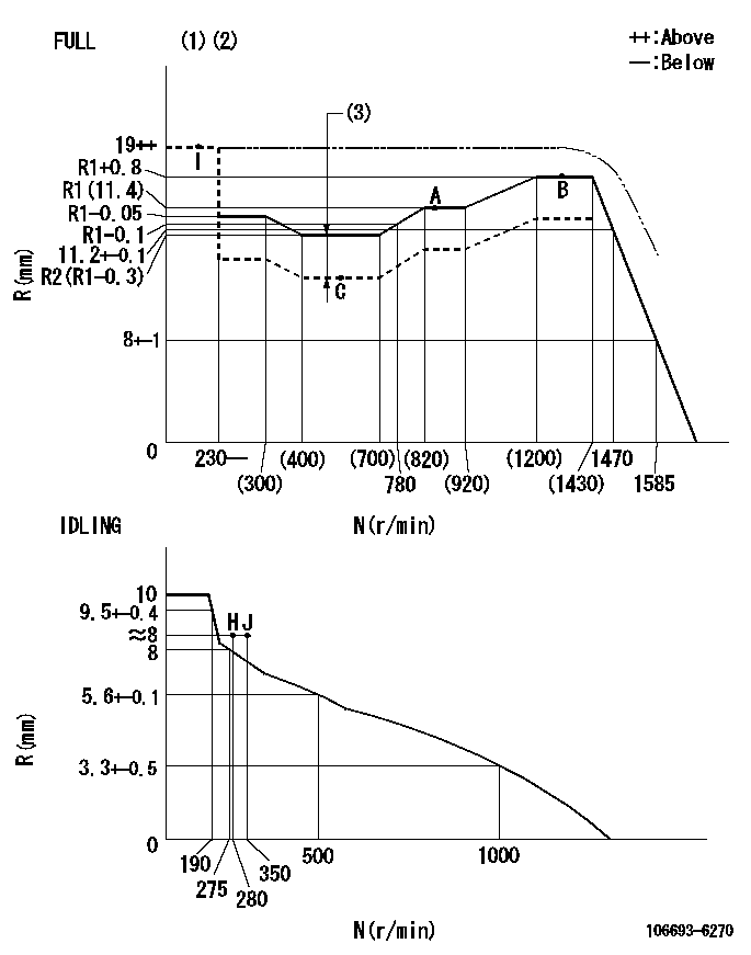
N:Pump speed
R:Rack position (mm)
(1)Torque cam stamping: T1
(2)Tolerance for racks not indicated: +-0.05mm.
(3)Boost compensator stroke: BCL
----------
T1=AG90 BCL=0.9+-0.1mm
----------
----------
T1=AG90 BCL=0.9+-0.1mm
----------
Timer adjustment
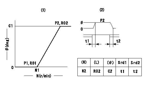
(1)Adjusting range
(2)Step response time
(N): Speed of the pump
(L): Load
(theta) Advance angle
(Srd1) Step response time 1
(Srd2) Step response time 2
1. Adjusting conditions for the variable timer
(1)Adjust the clearance between the pickup and the protrusion to L.
----------
L=1-0.2mm N2=800r/min C2=(6)deg t1=2.5--sec. t2=2.5--sec.
----------
N1=1400++r/min P1=0kPa(0kgf/cm2) P2=392kPa(4kgf/cm2) C1=6+-0.3deg R01=0/4load R02=4/4load
----------
L=1-0.2mm N2=800r/min C2=(6)deg t1=2.5--sec. t2=2.5--sec.
----------
N1=1400++r/min P1=0kPa(0kgf/cm2) P2=392kPa(4kgf/cm2) C1=6+-0.3deg R01=0/4load R02=4/4load
Speed control lever angle

F:Full speed
I:Idle
(1)Use the pin at R = aa
(2)Stopper bolt set position 'H'
----------
aa=35mm
----------
a=20deg+-5deg b=38deg+-3deg
----------
aa=35mm
----------
a=20deg+-5deg b=38deg+-3deg
Stop lever angle
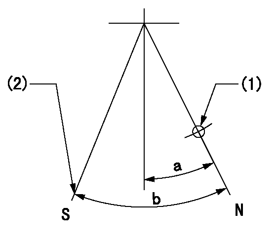
N:Pump normal
S:Stop the pump.
(1)Use the pin at R = aa
(2)Set the stopper bolt at rack position = bb, speed = cc and confirm non-injection.
----------
aa=40mm bb=1.5+-0.3mm cc=0r/min
----------
a=12deg+-5deg b=44deg+-5deg
----------
aa=40mm bb=1.5+-0.3mm cc=0r/min
----------
a=12deg+-5deg b=44deg+-5deg
0000001501 RACK SENSOR
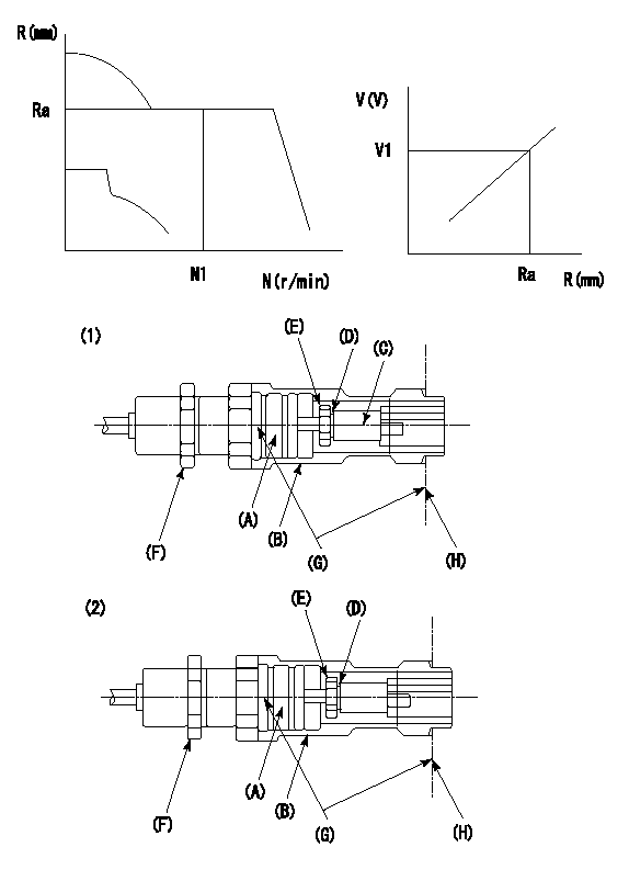
G:Red paint
H:Pump end face
P/N: part number of suitable shim
(1)Threaded type rack block
(2)Welded type rack block
Rack sensor adjustment
1. Threaded type rack sensor (-5*20, P type, no TICS rack limit).
(1)Screw in the bobbin (A) until it contacts the joint (B).
(2)Fix the pump lever.
(3)At speed N1 and rack position Ra, adjust the amount that the bobbin is screwed in so that the amp's output voltage is V1.
(4)Fix using the nut (F).
(5)Affix the caution plate to the upper part of the joint (B).
(6)Apply (G) at two places.
Connecting part between the joint (B) and the nut (F)
Connecting part between the end surface of the pump (H) and the joint (B)
2. Range for screw-in adjustment between the bobbin (A) and the joint (B) is 9 threads.
Screw in to the end from (the position where the bobbin (A) is rotated 9 turns).
Speed N1, rack position Ra, output voltage V1, rack sensor supply voltage 5+-0.01 (V)
----------
Ra=R1(11.4)+0.8mm N1=1350r/min V1=3+-0.01V
----------
----------
Ra=R1(11.4)+0.8mm N1=1350r/min V1=3+-0.01V
----------
Timing setting

(1)Pump vertical direction
(2)Position of timer's threaded hole at No 1 cylinder's beginning of injection
(3)B.T.D.C.: aa
(4)-
----------
aa=8deg
----------
a=(50deg)
----------
aa=8deg
----------
a=(50deg)
Information:
Reversal of Crankcase
Gently lay the crankcase on its side, then turn the crankcase upside down.
Resting the crankcase with the oil pan on the bottom can cause the oil pan to crack.
Reversal of crankcaseRemoval of Oil Pan And Oil Pan Gasket
(1) Unscrew the oil pan mounting bolts, and detach the oil pan.(2) Remove the oil pan gasket.
Removal of oil pan and oil gasketRemoval of Oil Pump
Unscrew the oil pump set bolt, and pull out the oil pump.
Removal of oil pumpRemoval of Camshaft
(1) Position the camshaft gear so that the two lightening holes are on the top and bottom, then remove the thrust plate mounting bolts using the socket. (2) Pull out the camshaft from the crankcase.
Removal of camshaft
Be careful not to damage the cams and bearing sections on the camshaft.
Removal of Front Plate
Unscrew the front plate mounting bolts, and dismount the front plate (together with the injection pump) from the crankcase.
Removal of front platePistons, Connecting Rods, Crankshaft and Crankcase
When replacing the crankcase, remove all accessories (relief valve and others) carefully from the crankcase, and reinstall them on a new crankcase.Laying Crankcase on Its Side
Gently lay the crankcase on its side.
Laying crankcase on its sideMeasurement of Thrust Clearance on Big-End of Connecting Rod
(1) Measure the clearance between the big-end of each connecting rod and the crankshaft (end play) with feeler gages. (2) If the measured clearance exceeds the limit value, replace the connecting rod.
Measurement of thrust clearance on big-end of connecting rodWeight Difference Among Connecting Rod Assemblies
When replacing connecting rods, make sure that all connecting rods have the same weight rank mark.
Weight rank mark on connecting rodRemoval of Connecting Rod Caps
(1) On each connecting rod and cap, put a mark indicating its cylinder No.(2) Remove the connecting rod caps.(3) For each removed connecting rod bearing (lower half), indicate the piston No. from which it was removed and the upper/lower identification. Be careful not to damage the bearings. Arrange the removed bearings in such a way that they can be reinstalled in their original positions during reassembly.
Removal of connecting rod capPreparation For Removal of Pistons
If carbon deposits are present at the upper sections of the cylinders, remove the carbon deposits with sandpaper and a cloth to facilitate piston removal.
Preparation for removal of pistonRemoval of Pistons
(1) Turn the crankshaft to bring the piston to be removed to the top dead center.(2) Using the wooden handle of a hammer, push the connecting rod on the cap contacting surface to remove the piston and connecting rod assembly from the top side of the cylinder.
Removal of pistonRemoval of Piston Ring
Using the piston ring pliers, remove the piston rings
Removal of piston ringRemoval of Piston Pins
Removal of piston pin(1) Using the snap ring pliers, remove the snap rings.(2) Pull out the piston pin, and separate the piston from the connecting rod.(3) If the piston pin cannot be remove easily, heat the piston with a piston heater or in hot water.Reversal of Crankcase
Gently stand the crankcase so that the oil pan mounting side faces up.
Reversal of crankcaseMeasurement of
Have questions with 106693-6270?
Group cross 106693-6270 ZEXEL
Isuzu
106693-6270
9 400 612 051
8943920570
INJECTION-PUMP ASSEMBLY
6HK1-TC
6HK1-TC