Information injection-pump assembly
ZEXEL
106693-6231
1066936231
ISUZU
8943905981
8943905981

Rating:
Service parts 106693-6231 INJECTION-PUMP ASSEMBLY:
1.
_
7.
COUPLING PLATE
8.
_
9.
_
11.
Nozzle and Holder
8-94390-519-0
12.
Open Pre:MPa(Kqf/cm2)
15.7{160}/22.1{225}
14.
NOZZLE
Include in #1:
106693-6231
as INJECTION-PUMP ASSEMBLY
Cross reference number
ZEXEL
106693-6231
1066936231
ISUZU
8943905981
8943905981
Zexel num
Bosch num
Firm num
Name
Calibration Data:
Adjustment conditions
Test oil
1404 Test oil ISO4113 or {SAEJ967d}
1404 Test oil ISO4113 or {SAEJ967d}
Test oil temperature
degC
40
40
45
Nozzle and nozzle holder
105780-8250
Bosch type code
1 688 901 101
Nozzle
105780-0120
Bosch type code
1 688 901 990
Nozzle holder
105780-2190
Opening pressure
MPa
20.7
Opening pressure
kgf/cm2
211
Injection pipe
Outer diameter - inner diameter - length (mm) mm 8-3-600
Outer diameter - inner diameter - length (mm) mm 8-3-600
Overflow valve
131424-8620
Overflow valve opening pressure
kPa
206
172
240
Overflow valve opening pressure
kgf/cm2
2.1
1.75
2.45
Tester oil delivery pressure
kPa
255
255
255
Tester oil delivery pressure
kgf/cm2
2.6
2.6
2.6
Direction of rotation (viewed from drive side)
Left L
Left L
Injection timing adjustment
Direction of rotation (viewed from drive side)
Left L
Left L
Injection order
1-5-3-6-
2-4
Pre-stroke
mm
3.6
3.57
3.63
Rack position
Point A R=A
Point A R=A
Beginning of injection position
Governor side NO.1
Governor side NO.1
Difference between angles 1
Cal 1-5 deg. 60 59.75 60.25
Cal 1-5 deg. 60 59.75 60.25
Difference between angles 2
Cal 1-3 deg. 120 119.75 120.25
Cal 1-3 deg. 120 119.75 120.25
Difference between angles 3
Cal 1-6 deg. 180 179.75 180.25
Cal 1-6 deg. 180 179.75 180.25
Difference between angles 4
Cyl.1-2 deg. 240 239.75 240.25
Cyl.1-2 deg. 240 239.75 240.25
Difference between angles 5
Cal 1-4 deg. 300 299.75 300.25
Cal 1-4 deg. 300 299.75 300.25
Injection quantity adjustment
Adjusting point
-
Rack position
11.3
Pump speed
r/min
700
700
700
Average injection quantity
mm3/st.
100
98
102
Max. variation between cylinders
%
0
-4
4
Basic
*
Fixing the rack
*
Standard for adjustment of the maximum variation between cylinders
*
Injection quantity adjustment_02
Adjusting point
Z
Rack position
8+-0.5
Pump speed
r/min
470
470
470
Average injection quantity
mm3/st.
12.5
9.3
15.7
Max. variation between cylinders
%
0
-13
13
Fixing the rack
*
Standard for adjustment of the maximum variation between cylinders
*
Injection quantity adjustment_03
Adjusting point
A
Rack position
R1(11.3)
Pump speed
r/min
700
700
700
Average injection quantity
mm3/st.
100
99
101
Basic
*
Fixing the lever
*
Boost pressure
kPa
57.3
57.3
Boost pressure
mmHg
430
430
Injection quantity adjustment_04
Adjusting point
B
Rack position
R1+0.5
Pump speed
r/min
1350
1350
1350
Average injection quantity
mm3/st.
90.5
86.5
94.5
Fixing the lever
*
Boost pressure
kPa
57.3
57.3
Boost pressure
mmHg
430
430
Boost compensator adjustment
Pump speed
r/min
500
500
500
Rack position
R2-1.25
Boost pressure
kPa
12
10.7
13.3
Boost pressure
mmHg
90
80
100
Boost compensator adjustment_02
Pump speed
r/min
500
500
500
Rack position
R2[R1-0.
15]
Boost pressure
kPa
44
44
44
Boost pressure
mmHg
330
330
330
Timer adjustment
Pump speed
r/min
900--
Advance angle
deg.
0
0
0
Load
3/5
Remarks
Start
Start
Timer adjustment_02
Pump speed
r/min
850
Advance angle
deg.
0.3
Load
3/5
Timer adjustment_03
Pump speed
r/min
-
Advance angle
deg.
1.5
1
2
Load
3/5
Remarks
Measure the actual speed.
Measure the actual speed.
Timer adjustment_04
Pump speed
r/min
1075
Advance angle
deg.
1.5
1
2
Load
4/5
Timer adjustment_05
Pump speed
r/min
1350
Advance angle
deg.
5.5
5
6
Load
4/5
Remarks
Finish
Finish
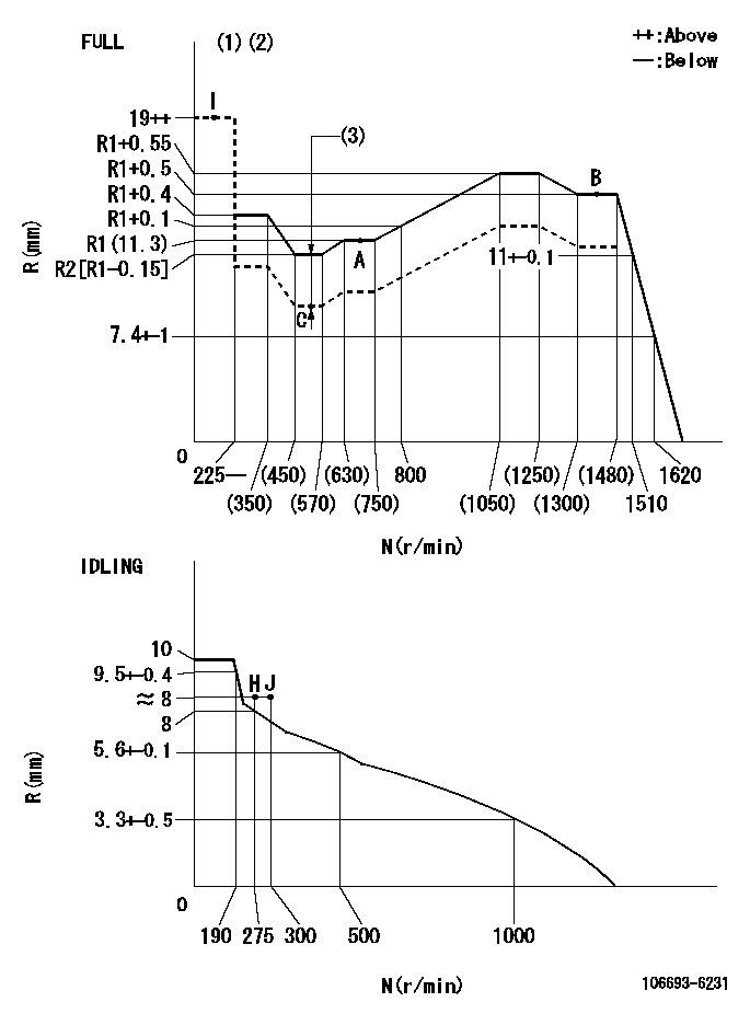
Test data Ex:
Governor adjustment

N:Pump speed
R:Rack position (mm)
(1)Torque cam stamping: T1
(2)Tolerance for racks not indicated: +-0.05mm.
(3)Boost compensator stroke: BCL
----------
T1=AD83 BCL=1.25+-0.1mm
----------
----------
T1=AD83 BCL=1.25+-0.1mm
----------
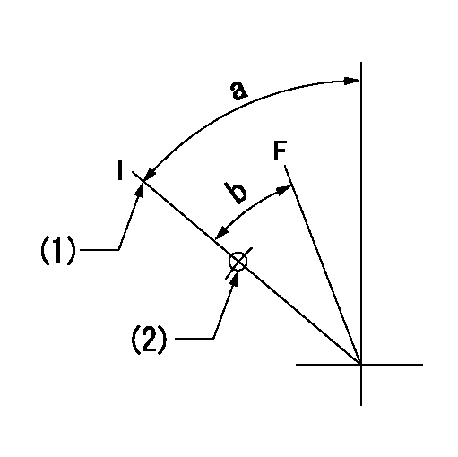
Speed control lever angle

F:Full speed
I:Idle
(1)Stopper bolt setting
(2)Use the hole at R = aa
----------
aa=35mm
----------
a=64deg+-5deg b=37deg+-3deg
----------
aa=35mm
----------
a=64deg+-5deg b=37deg+-3deg
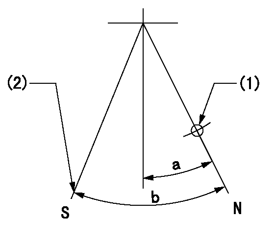
Stop lever angle

N:Pump normal
S:Stop the pump.
(1)Use the hole at R = aa
(2)Set the stopper bolt at rack position = bb, speed = cc and confirm non-injection.
----------
aa=55mm bb=1.5+-0.3mm cc=0r/min
----------
a=14deg+-5deg b=44deg+-5deg
----------
aa=55mm bb=1.5+-0.3mm cc=0r/min
----------
a=14deg+-5deg b=44deg+-5deg
Timing setting

(1)Pump vertical direction
(2)Position of timer's threaded hole at No 1 cylinder's beginning of injection
(3)B.T.D.C.: aa
(4)-
----------
aa=7deg
----------
a=(50deg)
----------
aa=7deg
----------
a=(50deg)
Information:
Refer to attached Rework Procedure.
SERVICE CLAIM ALLOWANCES
Product smu/age whichever comes first Caterpillar Dealer Suggested Customer Suggested
Parts % Labor Hrs% Parts % Labor Hrs% Parts % Labor Hrs%
*******Group 1*******
0-2000 hrs,
0-12 mo 100.0% 100.0% 0.0% 0.0% 0.0% 0.0%
2001-5000 hrs,
13-18 mo 100.0% 50.0% 0.0% 0.0% 0.0% 50.0%
5001-8000 hrs,
19-24 mo 100.0% 30.0% 0.0% 0.0% 0.0% 70.0%
This is a 4.0-hour job for Group 1
Product smu/age whichever comes first Caterpillar Dealer Suggested Customer Suggested
Parts % Labor Hrs% Parts % Labor Hrs% Parts % Labor Hrs%
*******Group 2*******
0-2000 hrs,
0-12 mo 100.0% 100.0% 0.0% 0.0% 0.0% 0.0%
2001-5000 hrs,
13-18 mo 100.0% 50.0% 0.0% 0.0% 0.0% 50.0%
5001-8000 hrs,
19-24 mo 100.0% 30.0% 0.0% 0.0% 0.0% 70.0%
This is a 4.0-hour job for Group 2
PARTS DISPOSITION
removed java code "affectDisposition"commented on Chints October 12 2006 Chints w.r.t CM000343756-->
Handle the parts in accordance with your Warranty Bulletin on warranty parts handling.
Rework Procedure
For the following units listed remove (6) 207-5248 Injector Rocker Arms, and replace with (6) 278-1365 Injector Rocker Arms.
For proper ?Disassembly & Assembly? instructions of the injector rocker arms please refer to the following Publications in SIS Web. (SENR9832-06 Testing & Adjusting-Finding Top Dead Center Position for No. 1 Piston), (SENR9832-06 Testing & Adjusting-Electronic Unit Injector Adjusting & Setting), and (SENR9832-06 Testing & Adjusting-Engine Valve Lash Inspect/Adjust).
Note: It is important that while installing the 278-1365 Injector Rocker Arms, that the engine is in the proper position (Top Dead Center and 180 degrees out) so the Injector Rocker Arms are properly adjusted and set. It is also important that during the installation of the Injector Rocker Arms that the Exhaust Valve, and Intake Valve lash settings be inspected and if needed re-set to factory specifications.
Note: During the rework process please inspect the 6I-0901 Rocker Arm Shafts for any signs of misalignment of the stud mounting holes, wear, damage, fretting etc. If damage is found to the shaft or if fretting or damage is found with any of the through bolt/stud mounting holes, the shaft is to be replaced, and reported against this service letter as contingent damage.