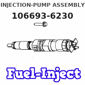
Information injection-pump assembly
ZEXEL
106693-6230
1066936230
ISUZU
8943905980
8943905980
Rating:
Service parts 106693-6230 INJECTION-PUMP ASSEMBLY:
1.
_
7.
COUPLING PLATE
8.
_
9.
_
11.
Nozzle and Holder
8-94390-519-0
12.
Open Pre:MPa(Kqf/cm2)
15.7{160}/22.1{225}
14.
NOZZLE
Include in #1:
106693-6230
as INJECTION-PUMP ASSEMBLY
Cross reference number
ZEXEL
106693-6230
1066936230
ISUZU
8943905980
8943905980
Zexel num
Bosch num
Firm num
Name
Calibration Data:
Adjustment conditions
Test oil
1404 Test oil ISO4113 or {SAEJ967d}
1404 Test oil ISO4113 or {SAEJ967d}
Test oil temperature
degC
40
40
45
Nozzle and nozzle holder
105780-8250
Bosch type code
1 688 901 101
Nozzle
105780-0120
Bosch type code
1 688 901 990
Nozzle holder
105780-2190
Opening pressure
MPa
20.7
Opening pressure
kgf/cm2
211
Injection pipe
Outer diameter - inner diameter - length (mm) mm 8-3-600
Outer diameter - inner diameter - length (mm) mm 8-3-600
Overflow valve
131424-8620
Overflow valve opening pressure
kPa
206
172
240
Overflow valve opening pressure
kgf/cm2
2.1
1.75
2.45
Tester oil delivery pressure
kPa
255
255
255
Tester oil delivery pressure
kgf/cm2
2.6
2.6
2.6
Direction of rotation (viewed from drive side)
Left L
Left L
Injection timing adjustment
Direction of rotation (viewed from drive side)
Left L
Left L
Injection order
1-5-3-6-
2-4
Pre-stroke
mm
3.6
3.57
3.63
Rack position
Point A R=A
Point A R=A
Beginning of injection position
Governor side NO.1
Governor side NO.1
Difference between angles 1
Cal 1-5 deg. 60 59.75 60.25
Cal 1-5 deg. 60 59.75 60.25
Difference between angles 2
Cal 1-3 deg. 120 119.75 120.25
Cal 1-3 deg. 120 119.75 120.25
Difference between angles 3
Cal 1-6 deg. 180 179.75 180.25
Cal 1-6 deg. 180 179.75 180.25
Difference between angles 4
Cyl.1-2 deg. 240 239.75 240.25
Cyl.1-2 deg. 240 239.75 240.25
Difference between angles 5
Cal 1-4 deg. 300 299.75 300.25
Cal 1-4 deg. 300 299.75 300.25
Injection quantity adjustment
Adjusting point
-
Rack position
11.2
Pump speed
r/min
700
700
700
Average injection quantity
mm3/st.
104.5
102.5
106.5
Max. variation between cylinders
%
0
-4
4
Basic
*
Fixing the rack
*
Standard for adjustment of the maximum variation between cylinders
*
Injection quantity adjustment_02
Adjusting point
Z
Rack position
8+-0.5
Pump speed
r/min
450
450
450
Average injection quantity
mm3/st.
12.5
9.3
15.7
Max. variation between cylinders
%
0
-13
13
Fixing the rack
*
Standard for adjustment of the maximum variation between cylinders
*
Injection quantity adjustment_03
Adjusting point
A
Rack position
R1(11.2)
Pump speed
r/min
700
700
700
Average injection quantity
mm3/st.
104.5
103.5
105.5
Basic
*
Fixing the lever
*
Boost pressure
kPa
64
64
Boost pressure
mmHg
480
480
Injection quantity adjustment_04
Adjusting point
B
Rack position
R1+0.5
Pump speed
r/min
1350
1350
1350
Average injection quantity
mm3/st.
94.5
90.5
98.5
Fixing the lever
*
Boost pressure
kPa
64
64
Boost pressure
mmHg
480
480
Boost compensator adjustment
Pump speed
r/min
500
500
500
Rack position
R2-1.3
Boost pressure
kPa
12
10.7
13.3
Boost pressure
mmHg
90
80
100
Boost compensator adjustment_02
Pump speed
r/min
500
500
500
Rack position
R2[R1-0.
15]
Boost pressure
kPa
50.7
50.7
50.7
Boost pressure
mmHg
380
380
380
Timer adjustment
Pump speed
r/min
900--
Advance angle
deg.
0
0
0
Load
3/5
Remarks
Start
Start
Timer adjustment_02
Pump speed
r/min
850
Advance angle
deg.
0.3
Load
3/5
Timer adjustment_03
Pump speed
r/min
-
Advance angle
deg.
1.5
1
2
Load
3/5
Remarks
Measure the actual speed.
Measure the actual speed.
Timer adjustment_04
Pump speed
r/min
1075
Advance angle
deg.
1.5
1
2
Load
4/5
Timer adjustment_05
Pump speed
r/min
1350
Advance angle
deg.
5.5
5
6
Load
4/5
Remarks
Finish
Finish
Test data Ex:
Governor adjustment
N:Pump speed
R:Rack position (mm)
(1)Torque cam stamping: T1
(2)Tolerance for racks not indicated: +-0.05mm.
(3)Boost compensator stroke: BCL
----------
T1=AD83 BCL=1.3+-0.1mm
----------
----------
T1=AD83 BCL=1.3+-0.1mm
----------
Speed control lever angle
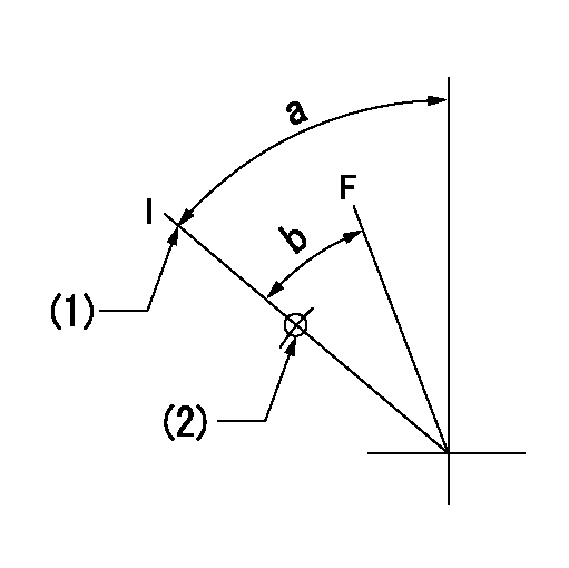
F:Full speed
I:Idle
(1)Stopper bolt setting
(2)Use the hole at R = aa
----------
aa=35mm
----------
a=64deg+-5deg b=37deg+-3deg
----------
aa=35mm
----------
a=64deg+-5deg b=37deg+-3deg
Stop lever angle
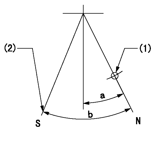
N:Pump normal
S:Stop the pump.
(1)Use the hole at R = aa
(2)Set the stopper bolt at rack position = bb, speed = cc and confirm non-injection.
----------
aa=55mm bb=1.5+-0.3mm cc=0r/min
----------
a=14deg+-5deg b=44deg+-5deg
----------
aa=55mm bb=1.5+-0.3mm cc=0r/min
----------
a=14deg+-5deg b=44deg+-5deg
Timing setting

(1)Pump vertical direction
(2)Position of timer's threaded hole at No 1 cylinder's beginning of injection
(3)B.T.D.C.: aa
(4)-
----------
aa=7deg
----------
a=(50deg)
----------
aa=7deg
----------
a=(50deg)
Information:
December 9, 2005
U-389
A-289
D-306
O-325
Partsstock action only PRODUCT IMPROVEMENT PROGRAM FOR REMOVINGCERTAIN FUEL INJECTORS FROM DEALERS PARTS STOCK
7750 PI70111
The information supplied in this serviceletter may not be valid after the termination date of this program. Donot perform the work outlined in this Service Letter after the terminationdate without first contacting your Caterpillar product analyst.TERMINATION DATE
March 31, 2006PROBLEM
A machining error can cause the valve body tocrack through the high-pressure line. This crack can result in fuel inthe engine oil.ACTION REQUIRED
All 10R-0957 unit injectors within serial numberrange 848368-850132 should be removed from parts stock. All 10R-0960, 10R-0961,and 10R-0963 within serial number range 188029-188914 should be removedfrom parts stock.SERVICE CLAIM ALLOWANCES
Submit one claim for all 10R0957, 10R0960, 10R0961,and 10R0963 Injectors removed from parts stock.PARTS DISPOSITION
All dealers are to make sure the outsideof the shipping container is marked PI70111.***** U.S. and Canadian Dealers *****Return all 10R0957, 10R0960, 10R0961, and 10R0963Injectors that are removed from parts stock and a copy of the claim to:Caterpillar Inc.
Attn: Supplier Recovery PI70111
Service Claims Room
8201 N. University
Peoria, IL 61615***** All Other Dealers *****Handle the parts in accordance with your WarrantyBulletin on warranty parts handling.