Information injection-pump assembly
BOSCH
F 01G 09U 097
f01g09u097
ZEXEL
106693-6200
1066936200
ISUZU
8943905950
8943905950

Rating:
Service parts 106693-6200 INJECTION-PUMP ASSEMBLY:
1.
_
7.
COUPLING PLATE
8.
_
9.
_
11.
Nozzle and Holder
8-94390-519-0
12.
Open Pre:MPa(Kqf/cm2)
15.7{160}/22.1{225}
14.
NOZZLE
Include in #1:
106693-6200
as INJECTION-PUMP ASSEMBLY
Cross reference number
BOSCH
F 01G 09U 097
f01g09u097
ZEXEL
106693-6200
1066936200
ISUZU
8943905950
8943905950
Zexel num
Bosch num
Firm num
Name
Calibration Data:
Adjustment conditions
Test oil
1404 Test oil ISO4113 or {SAEJ967d}
1404 Test oil ISO4113 or {SAEJ967d}
Test oil temperature
degC
40
40
45
Nozzle and nozzle holder
105780-8250
Bosch type code
1 688 901 101
Nozzle
105780-0120
Bosch type code
1 688 901 990
Nozzle holder
105780-2190
Opening pressure
MPa
20.7
Opening pressure
kgf/cm2
211
Injection pipe
Outer diameter - inner diameter - length (mm) mm 8-3-600
Outer diameter - inner diameter - length (mm) mm 8-3-600
Overflow valve
131424-8620
Overflow valve opening pressure
kPa
206
172
240
Overflow valve opening pressure
kgf/cm2
2.1
1.75
2.45
Tester oil delivery pressure
kPa
255
255
255
Tester oil delivery pressure
kgf/cm2
2.6
2.6
2.6
Direction of rotation (viewed from drive side)
Left L
Left L
Injection timing adjustment
Direction of rotation (viewed from drive side)
Left L
Left L
Injection order
1-5-3-6-
2-4
Pre-stroke
mm
3.6
3.57
3.63
Rack position
Point A R=A
Point A R=A
Beginning of injection position
Governor side NO.1
Governor side NO.1
Difference between angles 1
Cal 1-5 deg. 60 59.75 60.25
Cal 1-5 deg. 60 59.75 60.25
Difference between angles 2
Cal 1-3 deg. 120 119.75 120.25
Cal 1-3 deg. 120 119.75 120.25
Difference between angles 3
Cal 1-6 deg. 180 179.75 180.25
Cal 1-6 deg. 180 179.75 180.25
Difference between angles 4
Cyl.1-2 deg. 240 239.75 240.25
Cyl.1-2 deg. 240 239.75 240.25
Difference between angles 5
Cal 1-4 deg. 300 299.75 300.25
Cal 1-4 deg. 300 299.75 300.25
Injection quantity adjustment
Adjusting point
-
Rack position
11.7
Pump speed
r/min
700
700
700
Average injection quantity
mm3/st.
113
111
115
Max. variation between cylinders
%
0
-4
4
Basic
*
Fixing the rack
*
Standard for adjustment of the maximum variation between cylinders
*
Injection quantity adjustment_02
Adjusting point
Z
Rack position
8+-0.5
Pump speed
r/min
450
450
450
Average injection quantity
mm3/st.
12.5
9.3
15.7
Max. variation between cylinders
%
0
-13
13
Fixing the rack
*
Standard for adjustment of the maximum variation between cylinders
*
Injection quantity adjustment_03
Adjusting point
A
Rack position
R1(11.7)
Pump speed
r/min
700
700
700
Average injection quantity
mm3/st.
113
112
114
Basic
*
Fixing the lever
*
Boost pressure
kPa
69.3
69.3
Boost pressure
mmHg
520
520
Injection quantity adjustment_04
Adjusting point
B
Rack position
R1+0.75
Pump speed
r/min
1200
1200
1200
Average injection quantity
mm3/st.
110
106
114
Fixing the lever
*
Boost pressure
kPa
69.3
69.3
Boost pressure
mmHg
520
520
Boost compensator adjustment
Pump speed
r/min
500
500
500
Rack position
R2-1.7
Boost pressure
kPa
12
10.7
13.3
Boost pressure
mmHg
90
80
100
Boost compensator adjustment_02
Pump speed
r/min
500
500
500
Rack position
R2[R1-0.
2]
Boost pressure
kPa
56
56
56
Boost pressure
mmHg
420
420
420
Timer adjustment
Pump speed
r/min
900--
Advance angle
deg.
0
0
0
Load
3/5
Remarks
Start
Start
Timer adjustment_02
Pump speed
r/min
850
Advance angle
deg.
0.3
Load
3/5
Timer adjustment_03
Pump speed
r/min
-
Advance angle
deg.
1.5
1
2
Load
3/5
Remarks
Measure the actual speed.
Measure the actual speed.
Timer adjustment_04
Pump speed
r/min
1075
Advance angle
deg.
1.5
1
2
Load
4/5
Timer adjustment_05
Pump speed
r/min
1350
Advance angle
deg.
5.5
5
6
Load
4/5
Remarks
Finish
Finish
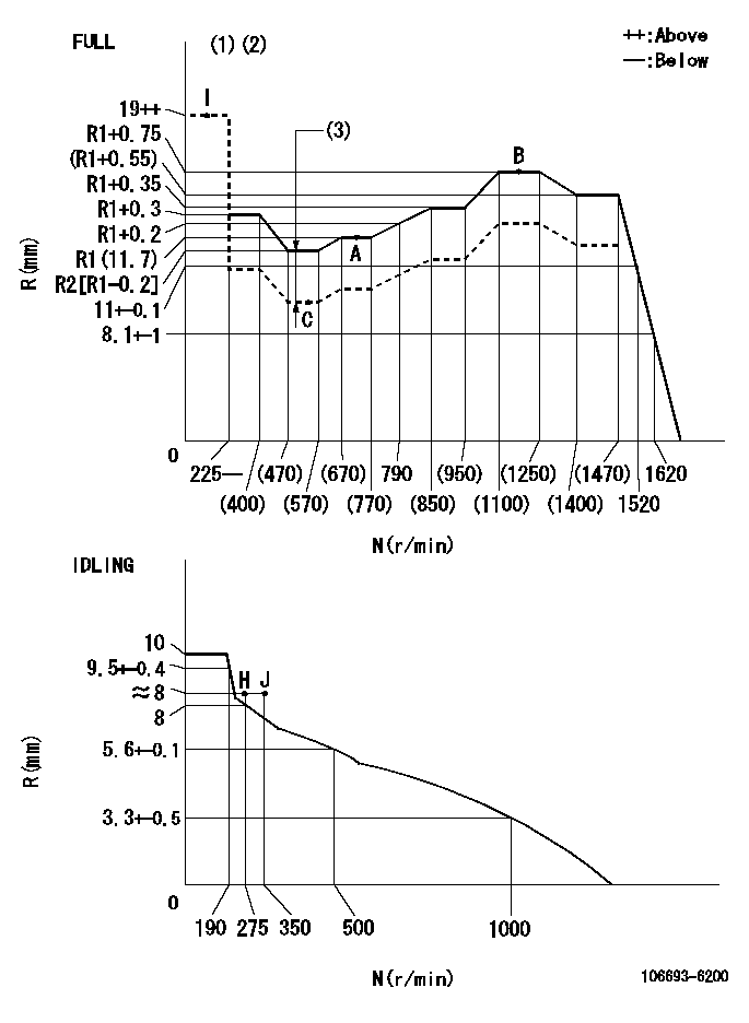
Test data Ex:
Governor adjustment

N:Pump speed
R:Rack position (mm)
(1)Torque cam stamping: T1
(2)Tolerance for racks not indicated: +-0.05mm.
(3)Boost compensator stroke: BCL
----------
T1=AD90 BCL=1.7+-0.1mm
----------
----------
T1=AD90 BCL=1.7+-0.1mm
----------
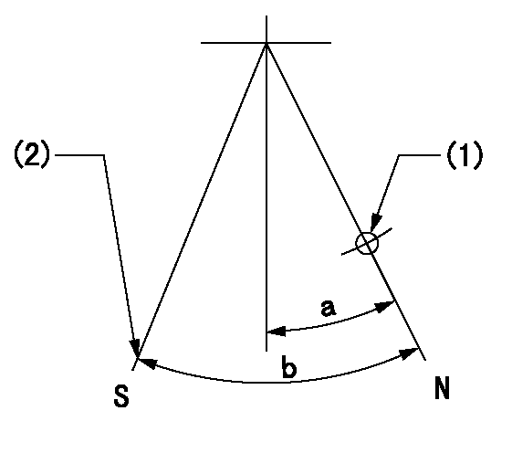
Speed control lever angle

F:Full speed
I:Idle
(1)Use the pin at R = aa
(2)Stopper bolt setting
----------
aa=35mm
----------
a=20deg+-5deg b=35deg+-3deg
----------
aa=35mm
----------
a=20deg+-5deg b=35deg+-3deg
Stop lever angle

N:Pump normal
S:Stop the pump.
(1)Use the pin at R = aa
(2)Set the stopper bolt at rack position = bb, speed = cc and confirm non-injection.
----------
aa=40mm bb=1.5+-0.3mm cc=0r/min
----------
a=12deg+-5deg b=44deg+-5deg
----------
aa=40mm bb=1.5+-0.3mm cc=0r/min
----------
a=12deg+-5deg b=44deg+-5deg
Timing setting

(1)Pump vertical direction
(2)Position of timer's threaded hole at No 1 cylinder's beginning of injection
(3)B.T.D.C.: aa
(4)-
----------
aa=7deg
----------
a=(50deg)
----------
aa=7deg
----------
a=(50deg)
Information:
Governor Actuator Mounting Replacement:
Removal Of The Previous Assembly
1. Disconnect linkage from cylinder and fuel pump, disassemble bracket from fuel pump lever.2. Remove cylinder from mounting plate, twist out rod end from cylinder.3. Remove mounting plate.Installing Of The New Linkage
1. Install 1433909, 8T4908, 8T4224, 9X6032, 8T4121 Linkage Assembly to engine block.2. Screw in U-joint of 1233885 Cylinder Rod as close as possible, tighten with 1426000 Nut, assemble cylinder with 8T1160 Bolts to the hinge.3. Assemble lever with washer and lock nut (1392085, 8T0389, 1392082, 8T4121), check free movement.4. Disconnect electrical connector from cylinder, turn on ignition, so that cylinder extends.5. Ensure pre-adjustment (overlapping of 1 mm) of U-joint and lever using the 8T4195 Stop Screw; tighten screw with nut (8T4133); See Illustration 2.6. Connect electrical connector to the cylinder and link up rod and lever with the 1233884 Pin.
Illustration 2Calibration
All adjustments have to be done with machine / engine at operating temperature
1. Start the engine.2. Plug-in PDT (portable diagnostic tool), choose menu "PROC" number 5 "ENGINE RPM" and number 6 "RPM DIFFERENCE". High And Low Idle Adjustment At Injection Pump:
1. Actuate the lever of the fuel injection pump by hand and adjust high and low idle by turning the corresponding stop screw at the fuel injection pump. If necessary fix the lever in the high idle position by use of a light spring to make adjustment easier:Set low idle to: 750 Rpm -20/+0 RpmSet high idle to : 2400 Rpm -0/+20 Rpm2. Make sure that when this is set a 1 mm spacer is fitted between the throttle lever and the high idle adjustment screw (see Illustration 3).3. Secure stop screw with locking nut. Seal setting with lockwire and lead seal, use your CAT dealer identification pliers.4. Disconnect electrical connector from the actuator (actuator piston extends completely).5. Stop the engine.6. Assemble and connect the 1413978 or 1397394, 9X8256, 1400277, 6V7743, 5C2890, 1107299, 1396903 Adjustable Rod, use the center hole at the fuel injection pump lever. Make sure that there is no contact between the fuel injection pump lever and the stop screw at high idle position.7. Start the engine.8. Adjust high idle setting with the rod:M312: high idle 2150 Rpm -0/+20 Rpm.M315: high idle 2400 Rpm -0/+20 Rpm.9. Secure the rod with the nuts at the ball joints.10. Mark the lock nut positions at the ball joints with a paint dot or using a felt-tip pen.11. Connect the electrical connector to the actuator.
Illustration 3Calibration/Adjustment Of The Engine
1. Press "F 1" key at the PDT for calibration.2. Choose item number 2 "CALIBRATION".3. Choose item number 1 "SPEED DIAL CAL".4. "MIN POSITION" setting, turn potentiometer on the panel until you receive the minimum voltage shown in the screen, press "ENTER".5. "MAX POSITION" setting, turn potentiometer until you receive maximum voltage shown in the screen, press "ENTER".6. You automatically get back into the previous menu, now choose number 2 "SPEED CAL".7. Change the low idle setting to 1020 Rpm by using the "UP- "or "DOWN-ARROW" keys at the PDT, when finished,