Information injection-pump assembly
ZEXEL
106693-6164
1066936164
ISUZU
8943900460
8943900460
Rating:
Service parts 106693-6164 INJECTION-PUMP ASSEMBLY:
1.
_
7.
COUPLING PLATE
8.
_
9.
_
11.
Nozzle and Holder
8-94390-049-1
12.
Open Pre:MPa(Kqf/cm2)
18.1{185}/22.1{225}
15.
NOZZLE SET
Include in #1:
106693-6164
as INJECTION-PUMP ASSEMBLY
Cross reference number
ZEXEL
106693-6164
1066936164
ISUZU
8943900460
8943900460
Zexel num
Bosch num
Firm num
Name
Calibration Data:
Adjustment conditions
Test oil
1404 Test oil ISO4113 or {SAEJ967d}
1404 Test oil ISO4113 or {SAEJ967d}
Test oil temperature
degC
40
40
45
Nozzle and nozzle holder
105780-8250
Bosch type code
1 688 901 101
Nozzle
105780-0120
Bosch type code
1 688 901 990
Nozzle holder
105780-2190
Opening pressure
MPa
20.7
Opening pressure
kgf/cm2
211
Injection pipe
Outer diameter - inner diameter - length (mm) mm 8-3-600
Outer diameter - inner diameter - length (mm) mm 8-3-600
Overflow valve
131424-8620
Overflow valve opening pressure
kPa
206
172
240
Overflow valve opening pressure
kgf/cm2
2.1
1.75
2.45
Tester oil delivery pressure
kPa
255
255
255
Tester oil delivery pressure
kgf/cm2
2.6
2.6
2.6
Direction of rotation (viewed from drive side)
Left L
Left L
Injection timing adjustment
Direction of rotation (viewed from drive side)
Left L
Left L
Injection order
1-5-3-6-
2-4
Pre-stroke
mm
3.6
3.57
3.63
Rack position
Point A R=A
Point A R=A
Beginning of injection position
Governor side NO.1
Governor side NO.1
Difference between angles 1
Cal 1-5 deg. 60 59.75 60.25
Cal 1-5 deg. 60 59.75 60.25
Difference between angles 2
Cal 1-3 deg. 120 119.75 120.25
Cal 1-3 deg. 120 119.75 120.25
Difference between angles 3
Cal 1-6 deg. 180 179.75 180.25
Cal 1-6 deg. 180 179.75 180.25
Difference between angles 4
Cyl.1-2 deg. 240 239.75 240.25
Cyl.1-2 deg. 240 239.75 240.25
Difference between angles 5
Cal 1-4 deg. 300 299.75 300.25
Cal 1-4 deg. 300 299.75 300.25
Injection quantity adjustment
Adjusting point
-
Rack position
11.4
Pump speed
r/min
700
700
700
Average injection quantity
mm3/st.
108
106
110
Max. variation between cylinders
%
0
-4
4
Basic
*
Fixing the rack
*
Standard for adjustment of the maximum variation between cylinders
*
Injection quantity adjustment_02
Adjusting point
Z
Rack position
8+-0.5
Pump speed
r/min
425
425
425
Average injection quantity
mm3/st.
12.5
9.3
15.7
Max. variation between cylinders
%
0
-10
10
Fixing the rack
*
Standard for adjustment of the maximum variation between cylinders
*
Injection quantity adjustment_03
Adjusting point
A
Rack position
R1(11.4)
Pump speed
r/min
700
700
700
Average injection quantity
mm3/st.
108
107
109
Basic
*
Fixing the lever
*
Boost pressure
kPa
72
72
Boost pressure
mmHg
540
540
Injection quantity adjustment_04
Adjusting point
B
Rack position
R1+0.9
Pump speed
r/min
1200
1200
1200
Average injection quantity
mm3/st.
108
104
112
Fixing the lever
*
Boost pressure
kPa
72
72
Boost pressure
mmHg
540
540
Boost compensator adjustment
Pump speed
r/min
525
525
525
Rack position
R2-1.7
Boost pressure
kPa
12
10.7
13.3
Boost pressure
mmHg
90
80
100
Boost compensator adjustment_02
Pump speed
r/min
525
525
525
Rack position
R1-0.2(R
2)
Boost pressure
kPa
58.7
58.7
58.7
Boost pressure
mmHg
440
440
440
Timer adjustment
Pump speed
r/min
900
Advance angle
deg.
0
0
0
Load
3/5
Remarks
Start
Start
Timer adjustment_02
Pump speed
r/min
850
Advance angle
deg.
0.3
Load
3/5
Timer adjustment_03
Pump speed
r/min
-
Advance angle
deg.
1.5
1
2
Load
3/5
Remarks
Measure the actual speed.
Measure the actual speed.
Timer adjustment_04
Pump speed
r/min
1075
Advance angle
deg.
1.5
1
2
Load
4/5
Timer adjustment_05
Pump speed
r/min
1350
Advance angle
deg.
5.5
5
6
Load
4/5
Remarks
Finish
Finish
Test data Ex:
Governor adjustment
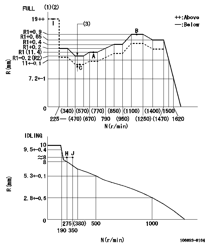
N:Pump speed
R:Rack position (mm)
(1)Torque cam stamping: T1
(2)Tolerance for racks not indicated: +-0.05mm.
(3)Boost compensator stroke: BCL
----------
T1=AC30 BCL=1.7+-0.1mm
----------
----------
T1=AC30 BCL=1.7+-0.1mm
----------
Speed control lever angle

F:Full speed
I:Idle
(1)Use the pin at R = aa
(2)Stopper bolt set position 'H'
----------
aa=35mm
----------
a=20deg+-5deg b=38deg+-3deg
----------
aa=35mm
----------
a=20deg+-5deg b=38deg+-3deg
Stop lever angle
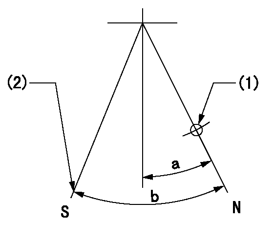
N:Pump normal
S:Stop the pump.
(1)Use the pin at R = aa
(2)Set the stopper bolt at rack position = bb, speed = cc and confirm non-injection.
----------
aa=40mm bb=1.5+-0.3mm cc=0r/min
----------
a=12deg+-5deg b=44deg+-5deg
----------
aa=40mm bb=1.5+-0.3mm cc=0r/min
----------
a=12deg+-5deg b=44deg+-5deg
Timing setting

(1)Pump vertical direction
(2)Position of timer's threaded hole at No 1 cylinder's beginning of injection
(3)B.T.D.C.: aa
(4)-
----------
aa=7deg
----------
a=(50deg)
----------
aa=7deg
----------
a=(50deg)
Information:
Adjusting the engine speeds
To adjust engine speed, remove the cooling fan and install the safety cover over the fan to prevent getting hurt. For speed adjustment specification, see 8-05.(1) The upper limit of engine speed can be adjusted with the HIGH-SPEED stopper bolt.This stopper bolt has been set properly and sealed in the factory before shipping of the engine. Never tamper with the seal unless it is necessary.(2) The lower limit of engine speed can be adjusted with the LOW-SPEED stopper bolt.(3) Never remove the sealing cap unnecessarily to adjust the torque spring set. For the proper disassembling procedure, see 4-02. CAUTION Warm up the engine (until coolant temperature rises up to 60°C or above) before adjusting engine speeds.(4) During running of the engine for speed adjustment, check the engine for gas leak, water leak, oil leak, and fuel leak.(5) After adjustment, perform engine acceleration and deceleration test to confirm that the engine is free from hunting and smoking.
HIGH-SPEED and LOW-SPEED Set BoltsChecking and adjustment of nozzles
To check and adjust the injection nozzles, use the following procedure:1. Injection start pressure(1) Remove the nozzle assembly to be tested from the cylinder head and set the nozzle on the nozzle tester.Perform air bleeding by moving the tester handle up and down.(2) Operate the handle at a speed of 60 rpm or more and read the gauge pressure of fuel injected from the nozzle.* Injection start pressure: 140 +10-0kgf/cm2 [13.7+1.0-0 MPa(3) If reading of gauge pressure is not within the specified range, disassemble the nozzle and vary thickness of the adjusting shim.Increasing or decreasing shim thickness by 0.1 mm will cause injection pressure to vary about 10 kgf/cm2 [0.98 MPa]
Testing Injection Start Pressure(4) When installing the nozzle, use the following values of tightening torque:* Nozzle tightening (to cylinder head) torque: 5.0 - 6.0 kgf m [49 - 59 N m]* Nozzle retaining nut tightening torque: 3.5 - 4.0 kgf m [34 - 39 N m]* Nozzle union collar tightening torque: 2.5 - 3.0 kgf m [25 - 29 N m]
Installing Nozzle Assembly2. Chattering testOperate the tester handle at a speed of about 1 stroke per second.(1) Needle valve oscillationIt is considered normal if the nozzle injects fuel mist, making intermittent sounds, and oscillations of the needle valve are transmitted to the handle.(2) State of fuel mist injectionThe nozzle should inject fuel mist straight in the direction of its axis. A nozzle is defective if it does not inject steadily or it injects fuel in several separate stripes.A nozzle is defective if it spills fuel accumulated on the bottom of the nozzle after chattering test. However, a very small drop of fuel remaining on the tip of nozzle after chattering test may be regarded as normal.
Charttering Test
After-spilling3. Injection testOperate the tester handle at a speed of 4 to 6 strokes per second.* A nozzle should inject fuel mist uniformly in the shape of a cone.4. Checking the compression pressure(1) Make sure of the following:(a) All of the engine oil level, air cleaner,