Information injection-pump assembly
ZEXEL
106693-6162
1066936162
ISUZU
8943949462
8943949462
Rating:
Service parts 106693-6162 INJECTION-PUMP ASSEMBLY:
1.
_
7.
COUPLING PLATE
8.
_
9.
_
11.
Nozzle and Holder
8-94394-213-0
12.
Open Pre:MPa(Kqf/cm2)
18.1{185}/22.1{225}
15.
NOZZLE SET
Include in #1:
106693-6162
as INJECTION-PUMP ASSEMBLY
Cross reference number
ZEXEL
106693-6162
1066936162
ISUZU
8943949462
8943949462
Zexel num
Bosch num
Firm num
Name
Calibration Data:
Adjustment conditions
Test oil
1404 Test oil ISO4113 or {SAEJ967d}
1404 Test oil ISO4113 or {SAEJ967d}
Test oil temperature
degC
40
40
45
Nozzle and nozzle holder
105780-8250
Bosch type code
1 688 901 101
Nozzle
105780-0120
Bosch type code
1 688 901 990
Nozzle holder
105780-2190
Opening pressure
MPa
20.7
Opening pressure
kgf/cm2
211
Injection pipe
Outer diameter - inner diameter - length (mm) mm 8-3-600
Outer diameter - inner diameter - length (mm) mm 8-3-600
Overflow valve
131424-8620
Overflow valve opening pressure
kPa
206
172
240
Overflow valve opening pressure
kgf/cm2
2.1
1.75
2.45
Tester oil delivery pressure
kPa
255
255
255
Tester oil delivery pressure
kgf/cm2
2.6
2.6
2.6
Direction of rotation (viewed from drive side)
Left L
Left L
Injection timing adjustment
Direction of rotation (viewed from drive side)
Left L
Left L
Injection order
1-5-3-6-
2-4
Pre-stroke
mm
3.6
3.57
3.63
Rack position
Point A R=A
Point A R=A
Beginning of injection position
Governor side NO.1
Governor side NO.1
Difference between angles 1
Cal 1-5 deg. 60 59.75 60.25
Cal 1-5 deg. 60 59.75 60.25
Difference between angles 2
Cal 1-3 deg. 120 119.75 120.25
Cal 1-3 deg. 120 119.75 120.25
Difference between angles 3
Cal 1-6 deg. 180 179.75 180.25
Cal 1-6 deg. 180 179.75 180.25
Difference between angles 4
Cyl.1-2 deg. 240 239.75 240.25
Cyl.1-2 deg. 240 239.75 240.25
Difference between angles 5
Cal 1-4 deg. 300 299.75 300.25
Cal 1-4 deg. 300 299.75 300.25
Injection quantity adjustment
Adjusting point
-
Rack position
11.4
Pump speed
r/min
700
700
700
Average injection quantity
mm3/st.
108
106
110
Max. variation between cylinders
%
0
-3
3
Basic
*
Fixing the rack
*
Standard for adjustment of the maximum variation between cylinders
*
Injection quantity adjustment_02
Adjusting point
Z
Rack position
8+-0.5
Pump speed
r/min
425
425
425
Average injection quantity
mm3/st.
12.5
9.3
15.7
Max. variation between cylinders
%
0
-13
13
Fixing the rack
*
Standard for adjustment of the maximum variation between cylinders
*
Injection quantity adjustment_03
Adjusting point
A
Rack position
R1(11.4)
Pump speed
r/min
700
700
700
Average injection quantity
mm3/st.
108
107
109
Basic
*
Fixing the lever
*
Boost pressure
kPa
72
72
Boost pressure
mmHg
540
540
Injection quantity adjustment_04
Adjusting point
B
Rack position
R1+0.9
Pump speed
r/min
1200
1200
1200
Average injection quantity
mm3/st.
108
104
112
Fixing the lever
*
Boost pressure
kPa
72
72
Boost pressure
mmHg
540
540
Boost compensator adjustment
Pump speed
r/min
525
525
525
Rack position
R2-1.7
Boost pressure
kPa
12
10.7
13.3
Boost pressure
mmHg
90
80
100
Boost compensator adjustment_02
Pump speed
r/min
525
525
525
Rack position
R1-0.2(R
2)
Boost pressure
kPa
58.7
58.7
58.7
Boost pressure
mmHg
440
440
440
Timer adjustment
Pump speed
r/min
900--
Advance angle
deg.
0
0
0
Load
3/5
Remarks
Start
Start
Timer adjustment_02
Pump speed
r/min
850
Advance angle
deg.
0.3
Load
3/5
Timer adjustment_03
Pump speed
r/min
-
Advance angle
deg.
1.5
1
2
Load
3/5
Remarks
Measure the actual speed.
Measure the actual speed.
Timer adjustment_04
Pump speed
r/min
1075
Advance angle
deg.
1.5
1
2
Load
4/5
Timer adjustment_05
Pump speed
r/min
1350
Advance angle
deg.
5.5
5
6
Load
4/5
Remarks
Finish
Finish
Test data Ex:
Governor adjustment
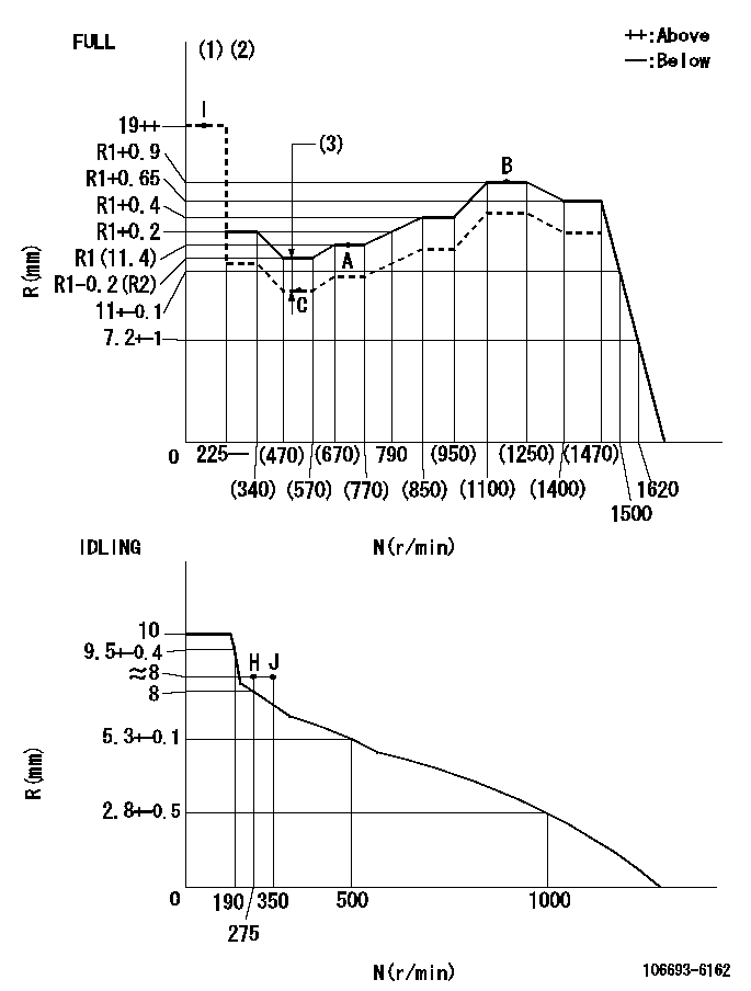
N:Pump speed
R:Rack position (mm)
(1)Torque cam stamping: T1
(2)Tolerance for racks not indicated: +-0.05mm.
(3)Boost compensator stroke: BCL
----------
T1=AC30 BCL=1.7+-0.1mm
----------
----------
T1=AC30 BCL=1.7+-0.1mm
----------
Speed control lever angle

F:Full speed
I:Idle
(1)Use the pin at R = aa
(2)Stopper bolt set position 'H'
----------
aa=35mm
----------
a=20deg+-5deg b=38deg+-3deg
----------
aa=35mm
----------
a=20deg+-5deg b=38deg+-3deg
Stop lever angle
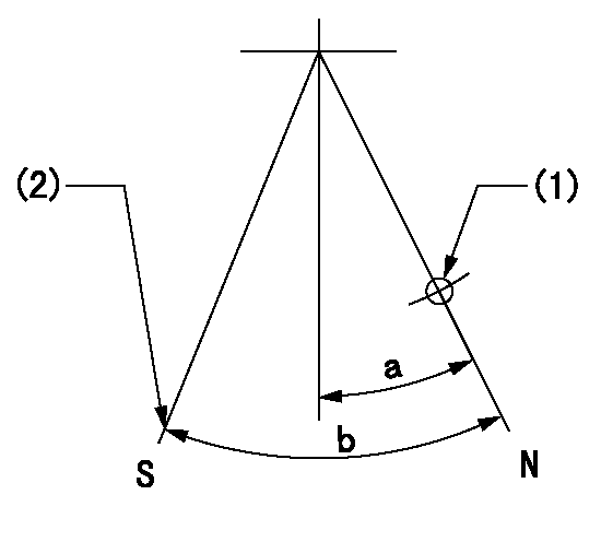
N:Pump normal
S:Stop the pump.
(1)Use the pin at R = aa
(2)Set the stopper bolt at rack position = bb, speed = cc and confirm non-injection.
----------
aa=40mm bb=1.5+-0.3mm cc=0r/min
----------
a=12deg+-5deg b=44deg+-5deg
----------
aa=40mm bb=1.5+-0.3mm cc=0r/min
----------
a=12deg+-5deg b=44deg+-5deg
Timing setting

(1)Pump vertical direction
(2)Position of timer's threaded hole at No 1 cylinder's beginning of injection
(3)B.T.D.C.: aa
(4)-
----------
aa=7deg
----------
a=(50deg)
----------
aa=7deg
----------
a=(50deg)
Information:
Disassembly and Reassembly of General Parts
Oil seals
When installing oil seals, observe the following.Installation of Oil Seals to Housings
(a) Check the seal lip for scratches and damage, and be sure to position the lip correctly.(b) Apply a small amount of grease to the periphery (housing contact surface) of the oil seal before installation.(c) Use an oil seal driver that guides the seal lip and presses the seal periphery, as shown in the diagram on the right. Striking the oil seal directly with a hammer causes seal damage and results in oil leaks.
Oil seal driverInstallation of Oil Seals to Shafts
(a) Apply grease to the oil seal lip.(b) Use an oil seal guide similar to the one shown in the diagram when installing an oil seal over the stepped portion, splines, threads or key grooves.
Oil seal guideO-rings
Use an O-ring guide similar to the one shown in the diagram when installing an O-ring over the stepped portion, splines, threads or key grooves. Be sure to apply a small amount of grease to the O-ring before installation.
O-ring guideBearings
(1) When installing a bearing, be sure to push the inner or outer race that fits into the installation position. (When the inner race fits into the installation position, push the inner race into position. When the outer race fits into the installation position, push the outer race into position.) Be sure to use a bearing driver similar to the one shown in the diagram.
Bearing driver(2) Use of a press minimizes the impact on the bearing and ensures proper installation.
Using press for bearing installationLock Plates
Be sure to bend lock plates. The diagram on the right shows the methods of bending representative lock plates.
Bending lock plateSplit Pins and Spring Pins
Generally, new split pins should be installed whenever split pins are removed. Be sure to bend split pins. Be sure to check spring pins for secure installation.