Information injection-pump assembly
BOSCH
9 400 617 933
9400617933
ZEXEL
106693-6150
1066936150
ISUZU
1156029210
1156029210

Rating:
Service parts 106693-6150 INJECTION-PUMP ASSEMBLY:
1.
_
7.
COUPLING PLATE
8.
_
9.
_
11.
Nozzle and Holder
12.
Open Pre:MPa(Kqf/cm2)
22.1{225}

15.
NOZZLE SET
Include in #1:
106693-6150
as INJECTION-PUMP ASSEMBLY
Cross reference number
BOSCH
9 400 617 933
9400617933
ZEXEL
106693-6150
1066936150
ISUZU
1156029210
1156029210
Zexel num
Bosch num
Firm num
Name
106693-6150
9 400 617 933
1156029210 ISUZU
INJECTION-PUMP ASSEMBLY
6RB1 K 14CA INJECTION PUMP ASSY PE6P,6PD PE
6RB1 K 14CA INJECTION PUMP ASSY PE6P,6PD PE
Calibration Data:
Adjustment conditions
Test oil
1404 Test oil ISO4113 or {SAEJ967d}
1404 Test oil ISO4113 or {SAEJ967d}
Test oil temperature
degC
40
40
45
Nozzle and nozzle holder
105780-8140
Bosch type code
EF8511/9A
Nozzle
105780-0000
Bosch type code
DN12SD12T
Nozzle holder
105780-2080
Bosch type code
EF8511/9
Opening pressure
MPa
17.2
Opening pressure
kgf/cm2
175
Injection pipe
Outer diameter - inner diameter - length (mm) mm 8-3-600
Outer diameter - inner diameter - length (mm) mm 8-3-600
Overflow valve
131424-0820
Overflow valve opening pressure
kPa
127
107
147
Overflow valve opening pressure
kgf/cm2
1.3
1.1
1.5
Tester oil delivery pressure
kPa
157
157
157
Tester oil delivery pressure
kgf/cm2
1.6
1.6
1.6
Direction of rotation (viewed from drive side)
Right R
Right R
Injection timing adjustment
Direction of rotation (viewed from drive side)
Right R
Right R
Injection order
1-4-2-6-
3-5
Pre-stroke
mm
3
2.95
3.05
Beginning of injection position
Drive side NO.1
Drive side NO.1
Difference between angles 1
Cal 1-4 deg. 60 59.5 60.5
Cal 1-4 deg. 60 59.5 60.5
Difference between angles 2
Cyl.1-2 deg. 120 119.5 120.5
Cyl.1-2 deg. 120 119.5 120.5
Difference between angles 3
Cal 1-6 deg. 180 179.5 180.5
Cal 1-6 deg. 180 179.5 180.5
Difference between angles 4
Cal 1-3 deg. 240 239.5 240.5
Cal 1-3 deg. 240 239.5 240.5
Difference between angles 5
Cal 1-5 deg. 300 299.5 300.5
Cal 1-5 deg. 300 299.5 300.5
Injection quantity adjustment
Adjusting point
A
Rack position
7.8
Pump speed
r/min
725
725
725
Average injection quantity
mm3/st.
130.5
128.5
132.5
Max. variation between cylinders
%
0
-3
3
Basic
*
Fixing the lever
*
Injection quantity adjustment_02
Adjusting point
-
Rack position
5.8+-0.5
Pump speed
r/min
385
385
385
Average injection quantity
mm3/st.
11.6
8.4
14.8
Max. variation between cylinders
%
0
-13
13
Fixing the rack
*
Remarks
Adjust only variation between cylinders; adjust governor according to governor specifications.
Adjust only variation between cylinders; adjust governor according to governor specifications.
Injection quantity adjustment_03
Adjusting point
D
Rack position
7.5
Pump speed
r/min
900
900
900
Average injection quantity
mm3/st.
128.5
122.5
134.5
Fixing the lever
*
Timer adjustment
Pump speed
r/min
(700)
Advance angle
deg.
0.5
Timer adjustment_02
Pump speed
r/min
890
Advance angle
deg.
1.7
1.2
2.2
Timer adjustment_03
Pump speed
r/min
-
Advance angle
deg.
4.5
4.5
4.5
Remarks
Measure the actual speed, stop
Measure the actual speed, stop
Test data Ex:
Governor adjustment

N:Pump speed
R:Rack position (mm)
(1)Target notch: K
(2)Tolerance for racks not indicated: +-0.05mm.
(3)Supplied with damper spring not set.
(4)Set idle sub-spring
----------
K=8
----------
----------
K=8
----------
Speed control lever angle
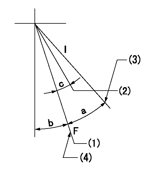
F:Full speed
I:Idle
(1)Pump speed = aa
(2)Pump speed = bb
(3)Stopper bolt setting
(4)Stopper bolt setting
----------
aa=900r/min bb=750r/min
----------
a=16deg+-5deg b=3deg+-5deg c=6deg+-5deg
----------
aa=900r/min bb=750r/min
----------
a=16deg+-5deg b=3deg+-5deg c=6deg+-5deg
Stop lever angle

N:Pump normal
S:Stop the pump.
----------
----------
a=10deg+-5deg b=53deg+-5deg
----------
----------
a=10deg+-5deg b=53deg+-5deg
Timing setting

(1)Pump vertical direction
(2)Position of timer's threaded hole at No 1 cylinder's beginning of injection
(3)B.T.D.C.: aa
(4)-
----------
aa=22deg
----------
a=(70deg)
----------
aa=22deg
----------
a=(70deg)
Information:
Water Pump
Disassembly of Water Pump
Inspection of Water Pump
If the inspection of the impeller and shaft finds abnormal noise or rough rotation, replace the assembly.
Inspection of impeller and shaft rotation conditionThermostat
Disassembly of Thermostat
Inspection of Thermostat
To test the thermostat operation, immerse the thermostat in a container filled with water, and heat the water while measuring the water temperature. Record the temperature at which the valve starts to open and the temperature at which the valve lift becomes 8 mm [0.3 in.] or more. (a) Stir the water in the container to ensure uniform temperature distribution.(b) When installing the thermostat, be sure to check the valve opening temperature indication stamped on the upper face of the thermostat mounting flange.
Inspection of thermostatThermo Switch
Inspection of Thermo Switch
Immerse the temperature sensor in oil, and measure the resistance while increasing the oil temperature. If the temperature measurement exceeds the standard value significantly, replace the thermo switch.
Since the inspection requires heating of oil to high temperatures, be careful not to get burns or start a fire.
Inspection of thermo switch
Have questions with 106693-6150?
Group cross 106693-6150 ZEXEL
Isuzu
Isuzu
106693-6150
9 400 617 933
1156029210
INJECTION-PUMP ASSEMBLY
6RB1
6RB1