Information injection-pump assembly
ZEXEL
106693-6130
1066936130
ISUZU
1156028851
1156028851
Rating:
Service parts 106693-6130 INJECTION-PUMP ASSEMBLY:
1.
_
7.
COUPLING PLATE
8.
_
9.
_
11.
Nozzle and Holder
1-15300-259-1
12.
Open Pre:MPa(Kqf/cm2)
15.7{160}/17.7{180}
15.
NOZZLE SET
Include in #1:
106693-6130
as INJECTION-PUMP ASSEMBLY
Cross reference number
ZEXEL
106693-6130
1066936130
ISUZU
1156028851
1156028851
Zexel num
Bosch num
Firm num
Name
Calibration Data:
Adjustment conditions
Test oil
1404 Test oil ISO4113 or {SAEJ967d}
1404 Test oil ISO4113 or {SAEJ967d}
Test oil temperature
degC
40
40
45
Nozzle and nozzle holder
105780-8140
Bosch type code
EF8511/9A
Nozzle
105780-0000
Bosch type code
DN12SD12T
Nozzle holder
105780-2080
Bosch type code
EF8511/9
Opening pressure
MPa
17.2
Opening pressure
kgf/cm2
175
Injection pipe
Outer diameter - inner diameter - length (mm) mm 8-3-600
Outer diameter - inner diameter - length (mm) mm 8-3-600
Overflow valve
134424-1920
Overflow valve opening pressure
kPa
127
107
147
Overflow valve opening pressure
kgf/cm2
1.3
1.1
1.5
Tester oil delivery pressure
kPa
157
157
157
Tester oil delivery pressure
kgf/cm2
1.6
1.6
1.6
Direction of rotation (viewed from drive side)
Right R
Right R
Injection timing adjustment
Direction of rotation (viewed from drive side)
Right R
Right R
Injection order
1-4-2-6-
3-5
Pre-stroke
mm
3
2.97
3.03
Beginning of injection position
Drive side NO.1
Drive side NO.1
Difference between angles 1
Cal 1-4 deg. 60 59.75 60.25
Cal 1-4 deg. 60 59.75 60.25
Difference between angles 2
Cyl.1-2 deg. 120 119.75 120.25
Cyl.1-2 deg. 120 119.75 120.25
Difference between angles 3
Cal 1-6 deg. 180 179.75 180.25
Cal 1-6 deg. 180 179.75 180.25
Difference between angles 4
Cal 1-3 deg. 240 239.75 240.25
Cal 1-3 deg. 240 239.75 240.25
Difference between angles 5
Cal 1-5 deg. 300 299.75 300.25
Cal 1-5 deg. 300 299.75 300.25
Injection quantity adjustment
Adjusting point
A
Rack position
7.5
Pump speed
r/min
700
700
700
Average injection quantity
mm3/st.
117
115
119
Max. variation between cylinders
%
0
-3
3
Basic
*
Fixing the lever
*
Injection quantity adjustment_02
Adjusting point
B
Rack position
8.3
Pump speed
r/min
1125
1125
1125
Average injection quantity
mm3/st.
139.2
137.2
141.2
Max. variation between cylinders
%
0
-4
4
Fixing the lever
*
Injection quantity adjustment_03
Adjusting point
-
Rack position
4.5+-0.5
Pump speed
r/min
225
225
225
Average injection quantity
mm3/st.
8
4.8
11.2
Max. variation between cylinders
%
0
-13
13
Fixing the rack
*
Remarks
Adjust only variation between cylinders; adjust governor according to governor specifications.
Adjust only variation between cylinders; adjust governor according to governor specifications.
Timer adjustment
Pump speed
r/min
950--
Advance angle
deg.
0
0
0
Load
3/4
Remarks
Start
Start
Timer adjustment_02
Pump speed
r/min
900
Advance angle
deg.
0.3
Load
3/4
Timer adjustment_03
Pump speed
r/min
1150
Advance angle
deg.
5.5
5
6
Load
4/4
Remarks
Finish
Finish
Test data Ex:
Governor adjustment
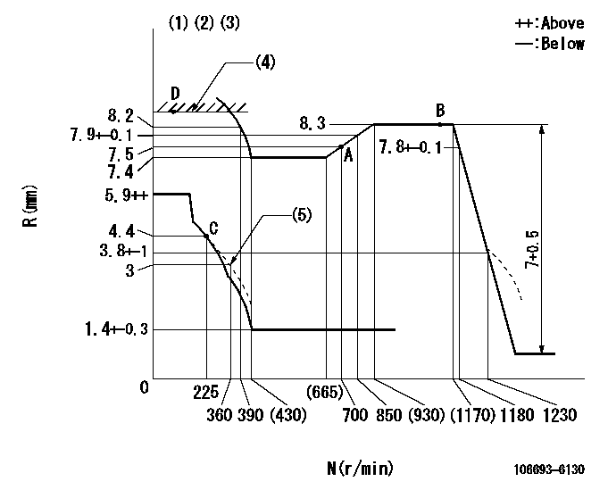
N:Pump speed
R:Rack position (mm)
(1)Lever ratio: RT
(2)Target shim dimension: TH
(3)Tolerance for racks not indicated: +-0.05mm.
(4)RACK LIMIT: RAL
(5)Damper spring setting
----------
RT=0.8 TH=2.7mm RAL=8.6+-0.1mm
----------
----------
RT=0.8 TH=2.7mm RAL=8.6+-0.1mm
----------
Speed control lever angle

F:Full speed
----------
----------
a=4deg+-5deg
----------
----------
a=4deg+-5deg
0000000901
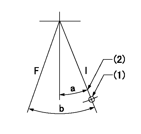
F:Full load
I:Idle
(1)Use the hole at R = aa
(2)Stopper bolt setting
----------
aa=73mm
----------
a=15deg+-5deg b=32deg+-3deg
----------
aa=73mm
----------
a=15deg+-5deg b=32deg+-3deg
Stop lever angle

N:Pump normal
S:Stop the pump.
----------
----------
a=52deg+-5deg b=64deg+-5deg
----------
----------
a=52deg+-5deg b=64deg+-5deg
0000001501 GOVERNOR TORQUE CONTROL

Dr:Torque control stroke
(A): Without torque control spring capsule
1. Adjustment procedures
(1)Procedure is the same as that for the RFD (former type), except that the positive torque control stroke must be determined at the full lever setting.
2. Procedures for adjustment
(1)Remove the torque control spring capsule.
(2)Operate the pump at approximately N1. (End of idling spring operation < N1.)
(3)Tilt the lever to the full side.
(4)Set so that R = RF.
(5)Increase the speed by pushing in the screw (attached to the bracket on the rear of the tension lever) through the adjusting window.
(6)Adjust so that the torque control stroke Dr1 can be obtained.
(7)Align N2 and N3 with the torque control spring capsule.
3. Final confirmation
(1)After final confirmation, temporarily set the load lever to N = N1, R = idling position.
(2)From this condition, increase speed to N = N4.
(3)Confirm that positive torque control stroke is Dr2.
----------
N1=500r/min N2=(665)r/min N3=(930)r/min N4=1100r/min RF=7.4mm Dr1=0.9mm Dr2=0+0.3mm
----------
----------
N1=500r/min N2=(665)r/min N3=(930)r/min N4=1100r/min RF=7.4mm Dr1=0.9mm Dr2=0+0.3mm
----------
Timing setting

(1)Pump vertical direction
(2)Position of timer's threaded hole at No 1 cylinder's beginning of injection
(3)B.T.D.C.: aa
(4)-
----------
aa=13deg
----------
a=(70deg)
----------
aa=13deg
----------
a=(70deg)
Information:
Installation of Oil Seal Case
(1) Coat the outside surface of the oil seal with engine oil.(2) Install the oil seal on the oil seal case.(3) Coat the lip of the oil seal with engine oil.(4) Install the O-ring into the oil seal case, and install the oil seal case on the flywheel housing. The oil seal case must be installed with the "Q" mark facing up.(5) Secure the oil seal case with the bolts.
Installation of oil seal caseInstallation of Flywheel
(1) Install the flywheel to the crankshaft by aligning the hole with the dowel pin on the back-end of the crankshaft.(2) Place the washer and tighten the four bolts to the specified torque.
Installation of flywheelMeasurement of Flywheel Axial and Radial Runouts
Measure the flywheel runout with the flywheel installed to the crankshaft. If the standard value is exceeded, check the bolts for tightening condition and the mounting face for adhesion of foreign particles.
Measurement of face runout and circular runoutCylinder Head and Valve Mechanisms
Installation of Valve Stem Seals
(1) Apply engine oil to the valve stem, and insert it into the valve guide.(2) Place a new stem seal on the valve guide.(3) Using the stem seal installer, install the stem seal to the valve guide, making use of the valve stem as a guide.
Installation of valve stem sealInstallation of Valves and Valve Springs
(1) Place the valve spring and retainer on the valve guide, and install the valve cotter using the valve spring pusher.
Excessive compression of the valve spring can cause the retainer to contact the stem seal and damage the seal.
Installation of valve and valve spring(2) Using a soft-faced hammer, tap the top of the valve stem several times to make sure that the spring and valve cotter are securely installed.
Confirmation of secure valve cotter installationInstallation of Cylinder Head Gasket
(1) Make sure that the top face of the crankcase and piston upper surfaces are clean and free of dust.(2) Place a new gasket of the crankcase, making sure that the dowel pins on the top face of the crankcase enter the holes in the gasket.
Do not use a liquid gasket.
Installation of cylinder head gasketInstallation of Cylinder Head
Place the cylinder head on the head gasket, making sure that the dowel pins on the top face of the crankcase enters the holes in the cylinder head.
Installation of cylinder headTightening of Cylinder Head Bolts
Tighten the cylinder head bolts, following the tightening sequence shown in the diagram two or three times before reaching the specified torque.
Cylinder head bolt tightening sequenceAssembly of Rocker Arm and Rocker Shaft Assembly
When installing the rocker arms, make sure that the shaft assembly marks face the front of the engine, as shown in the diagram. After the assembly, make sure that the rocker arms move smoothly.
Assembly of rocker shaft assemblyInstallation of Pushrods
(1) Insert the pushrods in the cylinder head through the pushrod holes.(2) Make sure that the ball end of each pushrod rests securely on the curved surface of the tappet.Installation of Rocker Shaft Assembly
(1) Install the valve caps.(2) Tighten the rocker