Information injection-pump assembly
ZEXEL
106693-6120
1066936120
ISUZU
1156028841
1156028841
Rating:
Cross reference number
ZEXEL
106693-6120
1066936120
ISUZU
1156028841
1156028841
Zexel num
Bosch num
Firm num
Name
Calibration Data:
Adjustment conditions
Test oil
1404 Test oil ISO4113 or {SAEJ967d}
1404 Test oil ISO4113 or {SAEJ967d}
Test oil temperature
degC
40
40
45
Nozzle and nozzle holder
105780-8140
Bosch type code
EF8511/9A
Nozzle
105780-0000
Bosch type code
DN12SD12T
Nozzle holder
105780-2080
Bosch type code
EF8511/9
Opening pressure
MPa
17.2
Opening pressure
kgf/cm2
175
Injection pipe
Outer diameter - inner diameter - length (mm) mm 8-3-600
Outer diameter - inner diameter - length (mm) mm 8-3-600
Overflow valve
134424-1920
Overflow valve opening pressure
kPa
127
107
147
Overflow valve opening pressure
kgf/cm2
1.3
1.1
1.5
Tester oil delivery pressure
kPa
157
157
157
Tester oil delivery pressure
kgf/cm2
1.6
1.6
1.6
Direction of rotation (viewed from drive side)
Right R
Right R
Injection timing adjustment
Direction of rotation (viewed from drive side)
Right R
Right R
Injection order
1-4-2-6-
3-5
Pre-stroke
mm
3
2.97
3.03
Beginning of injection position
Drive side NO.1
Drive side NO.1
Difference between angles 1
Cal 1-4 deg. 60 59.75 60.25
Cal 1-4 deg. 60 59.75 60.25
Difference between angles 2
Cyl.1-2 deg. 120 119.75 120.25
Cyl.1-2 deg. 120 119.75 120.25
Difference between angles 3
Cal 1-6 deg. 180 179.75 180.25
Cal 1-6 deg. 180 179.75 180.25
Difference between angles 4
Cal 1-3 deg. 240 239.75 240.25
Cal 1-3 deg. 240 239.75 240.25
Difference between angles 5
Cal 1-5 deg. 300 299.75 300.25
Cal 1-5 deg. 300 299.75 300.25
Injection quantity adjustment
Adjusting point
A
Rack position
8.5
Pump speed
r/min
700
700
700
Average injection quantity
mm3/st.
117
115
119
Max. variation between cylinders
%
0
-3
3
Basic
*
Fixing the lever
*
Injection quantity adjustment_02
Adjusting point
B
Rack position
9.3
Pump speed
r/min
1125
1125
1125
Average injection quantity
mm3/st.
139.1
137.1
141.1
Max. variation between cylinders
%
0
-4
4
Fixing the lever
*
Injection quantity adjustment_03
Adjusting point
-
Rack position
5.5+-0.5
Pump speed
r/min
225
225
225
Average injection quantity
mm3/st.
8
4.8
11.2
Max. variation between cylinders
%
0
-13
13
Fixing the rack
*
Remarks
Adjust only variation between cylinders; adjust governor according to governor specifications.
Adjust only variation between cylinders; adjust governor according to governor specifications.
Timer adjustment
Pump speed
r/min
950--
Advance angle
deg.
0
0
0
Load
3/4
Remarks
Start
Start
Timer adjustment_02
Pump speed
r/min
900
Advance angle
deg.
0.3
Load
3/4
Timer adjustment_03
Pump speed
r/min
1150
Advance angle
deg.
5.5
5
6
Load
4/4
Remarks
Finish
Finish
Test data Ex:
Governor adjustment
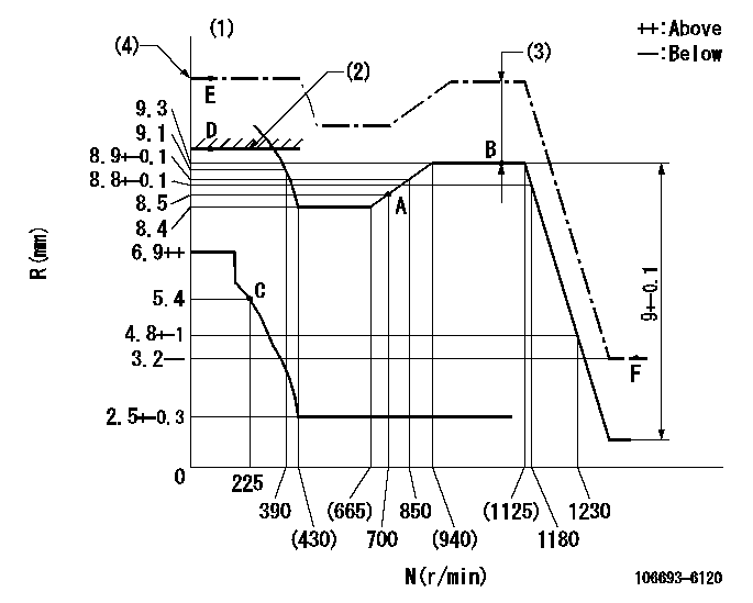
N:Pump speed
R:Rack position (mm)
(1)Tolerance for racks not indicated: +-0.05mm.
(2)RACK LIMIT: RAL
(3)SFA lever setting: RA at (N = N1)
(4)R1 (actual measurement)
----------
RAL=9.6+-0.1mm RA=1.5+-0.1mm N1=1125r/min
----------
----------
RAL=9.6+-0.1mm RA=1.5+-0.1mm N1=1125r/min
----------
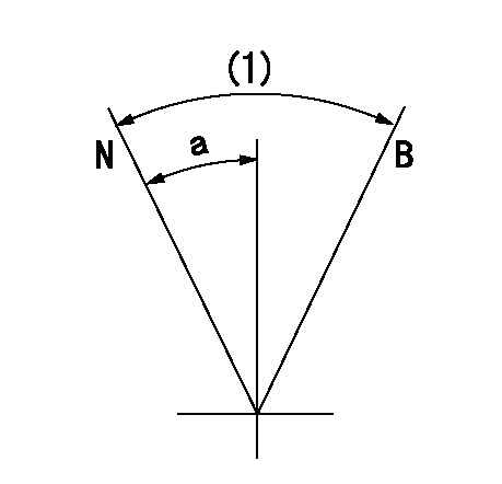
Speed control lever angle

F:Full speed
----------
----------
a=4.5deg+-5deg
----------
----------
a=4.5deg+-5deg
0000000901
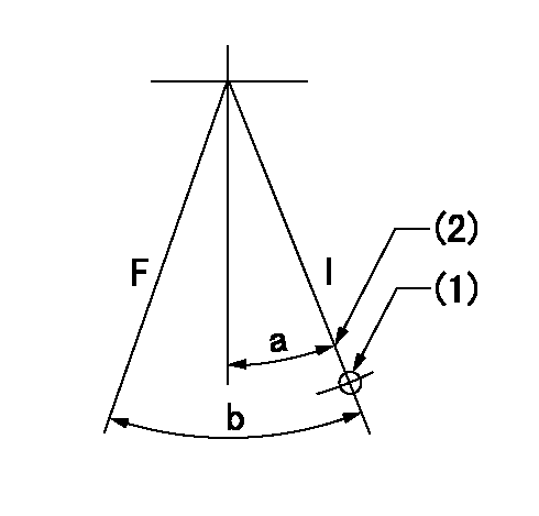
F:Full load
I:Idle
(1)Use the hole at R = aa
(2)Stopper bolt setting
----------
aa=73mm
----------
a=15deg+-5deg b=32deg+-3deg
----------
aa=73mm
----------
a=15deg+-5deg b=32deg+-3deg
Stop lever angle
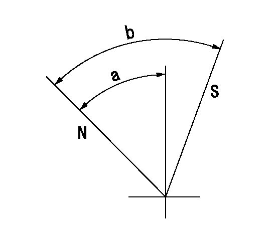
N:Pump normal
S:Stop the pump.
----------
----------
a=35deg+-5deg b=73deg+-5deg
----------
----------
a=35deg+-5deg b=73deg+-5deg
0000001101
N:Normal
B:When boosted
(1)(Actual measurement)
----------
----------
a=(20deg)
----------
----------
a=(20deg)
0000001501 GOVERNOR TORQUE CONTROL

Dr:Torque control stroke
(A): Without torque control spring capsule
1. Adjustment procedures
(1)Procedure is the same as that for the RFD (former type), except that the positive torque control stroke must be determined at the full lever setting.
2. Procedures for adjustment
(1)Remove the torque control spring capsule.
(2)Operate the pump at approximately N1. (End of idling spring operation < N1.)
(3)Tilt the lever to the full side.
(4)Set so that R = RF.
(5)Increase the speed by pushing in the screw (attached to the bracket on the rear of the tension lever) through the adjusting window.
(6)Adjust so that the torque control stroke Dr1 can be obtained.
(7)Align N2 and N3 with the torque control spring capsule.
3. Final confirmation
(1)After final confirmation, temporarily set the load lever to N = N1, R = idling position.
(2)From this condition, increase speed to N = N4.
(3)Confirm that positive torque control stroke is Dr2.
----------
N1=500r/min N2=(665)r/min N3=(940)r/min N4=1100r/min RF=8.4mm Dr1=0.9mm Dr2=0+0.3mm
----------
----------
N1=500r/min N2=(665)r/min N3=(940)r/min N4=1100r/min RF=8.4mm Dr1=0.9mm Dr2=0+0.3mm
----------
Timing setting

(1)Pump vertical direction
(2)Position of timer's threaded hole at No 1 cylinder's beginning of injection
(3)B.T.D.C.: aa
(4)-
----------
aa=13deg
----------
a=(70deg)
----------
aa=13deg
----------
a=(70deg)
Information:
Determination Of Overhaul Timing
Generally, the engine needs an overhaul when the compression pressure of the engine becomes low, and the amounts of engine oil consumption and blow-by gas increase.Reduced power output, increased fuel consumption, low oil pressure, difficult in starting, and increased operating noise are also signs that suggest the need for an overhaul; however, since these problems can be caused by various factors, they do not serve as reliable criteria for determining the need for an overhaul.Reduced compression pressure manifests a variety of symptoms, thus making it difficult to accurately determine when the engine needs an overhaul. The following shows typical problems caused by reduced compression pressure.(1) Decreased output power(2) Increased fuel consumption(3) Increased engine oil consumption(4) Increased blow-by gas from breather due to leakage of combustion gas through worn cylinder liners and piston rings(5) Increased gas leakage due to poor seating of inlet and exhaust valves(6) Difficulty in starting(7) Increased noise from engine parts(8) Abnormal exhaust color after warm-up operationThe engine can exhibit these conditions in various combinations.Some of these problems are directly caused by worn engine parts, while others are not.Phenomena described in (2) and (6) can also result from improper injection volume, incorrect fuel injection timing, worn plungers, defective nozzles, and faulty conditions of electrical devices such as battery, starter and alternator.The most valid reason to overhaul an engine is a decrease in the compression pressure due to worn cylinder liners and pistons, as described in (4), and once this is determined, other symptoms should be taken into consideration in order to make the final judgement of whether the engine needs an overhaul.Measurement of Compression Pressure
Measurement of compression pressurePreparation For Inspection
Check the following before inspection.(1) Make sure that the engine oil, air cleaner, starter, battery, etc. are in normal operating condition.Inspection
(1) Move the control lever to the Stop position.(2) Remove the glow plugs from all cylinders, and attach the gage adapter and compression gage to the cylinder to be tested.(3) Crank the engine with the starter, and read the compression gage indication when the indication stabilizes.(4) If the measured compression pressure is lower than the limit, consider overhauling the engine.
(a) Measure the compression pressure in all cylinders.(b) As compression pressure varies with the engine speed, measure the engine speed at the same time.
Measure the compression pressure while the engine is running at 150 to 200 min-1. The oil and coolant temperatures should be between 20 and 30 °C [68 and 86°F].
It is important to regularly check the compression pressure so that you can tell the difference. * New or overhauled engines have slightly higher compression pressure.* The compression pressure settles to the standard value as the piston rings and valve seats fit in.* As wear progresses further, the compression pressure drops.