Information injection-pump assembly
ZEXEL
106693-6110
1066936110
ISUZU
1156028910
1156028910
Rating:
Service parts 106693-6110 INJECTION-PUMP ASSEMBLY:
1.
_
7.
COUPLING PLATE
8.
_
9.
_
11.
Nozzle and Holder
12.
Open Pre:MPa(Kqf/cm2)
22.1(225)

15.
NOZZLE SET
Include in #1:
106693-6110
as INJECTION-PUMP ASSEMBLY
Cross reference number
ZEXEL
106693-6110
1066936110
ISUZU
1156028910
1156028910
Zexel num
Bosch num
Firm num
Name
Calibration Data:
Adjustment conditions
Test oil
1404 Test oil ISO4113 or {SAEJ967d}
1404 Test oil ISO4113 or {SAEJ967d}
Test oil temperature
degC
40
40
45
Nozzle and nozzle holder
105780-8140
Bosch type code
EF8511/9A
Nozzle
105780-0000
Bosch type code
DN12SD12T
Nozzle holder
105780-2080
Bosch type code
EF8511/9
Opening pressure
MPa
17.2
Opening pressure
kgf/cm2
175
Injection pipe
Outer diameter - inner diameter - length (mm) mm 8-3-600
Outer diameter - inner diameter - length (mm) mm 8-3-600
Overflow valve
134424-1920
Overflow valve opening pressure
kPa
127
107
147
Overflow valve opening pressure
kgf/cm2
1.3
1.1
1.5
Tester oil delivery pressure
kPa
157
157
157
Tester oil delivery pressure
kgf/cm2
1.6
1.6
1.6
Direction of rotation (viewed from drive side)
Right R
Right R
Injection timing adjustment
Direction of rotation (viewed from drive side)
Right R
Right R
Injection order
1-4-2-6-
3-5
Pre-stroke
mm
3
2.95
3.05
Beginning of injection position
Drive side NO.1
Drive side NO.1
Difference between angles 1
Cal 1-4 deg. 60 59.5 60.5
Cal 1-4 deg. 60 59.5 60.5
Difference between angles 2
Cyl.1-2 deg. 120 119.5 120.5
Cyl.1-2 deg. 120 119.5 120.5
Difference between angles 3
Cal 1-6 deg. 180 179.5 180.5
Cal 1-6 deg. 180 179.5 180.5
Difference between angles 4
Cal 1-3 deg. 240 239.5 240.5
Cal 1-3 deg. 240 239.5 240.5
Difference between angles 5
Cal 1-5 deg. 300 299.5 300.5
Cal 1-5 deg. 300 299.5 300.5
Injection quantity adjustment
Adjusting point
A
Rack position
8.9
Pump speed
r/min
650
650
650
Average injection quantity
mm3/st.
133.9
131.9
135.9
Max. variation between cylinders
%
0
-3
3
Basic
*
Fixing the lever
*
Injection quantity adjustment_02
Adjusting point
B
Rack position
5.3+-0.5
Pump speed
r/min
225
225
225
Average injection quantity
mm3/st.
12.6
9.4
15.8
Max. variation between cylinders
%
0
-13
13
Fixing the rack
*
Timer adjustment
Pump speed
r/min
(830)
Advance angle
deg.
0
0
0
Remarks
Start
Start
Timer adjustment_02
Pump speed
r/min
1100
Advance angle
deg.
5
4.5
5.5
Remarks
Finish
Finish
Test data Ex:
Governor adjustment
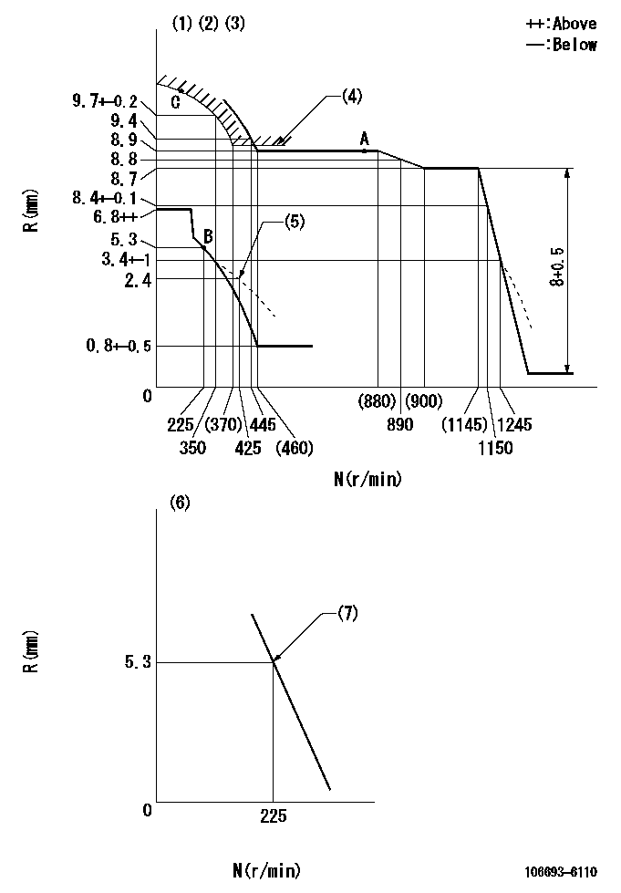
N:Pump speed
R:Rack position (mm)
(1)Lever ratio: RT
(2)Target shim dimension: TH
(3)Tolerance for racks not indicated: +-0.05mm.
(4)Excess fuel setting for starting: SXL
(5)Damper spring setting
(6)Variable speed specification: idling adjustment
(7)Main spring setting
----------
RT=1 TH=1.7mm SXL=9.2+-0.1mm
----------
----------
RT=1 TH=1.7mm SXL=9.2+-0.1mm
----------
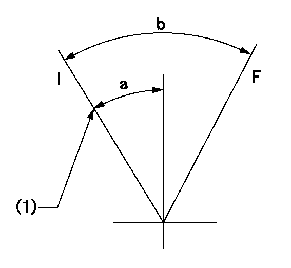
Speed control lever angle
F:Full speed
I:Idle
(1)Stopper bolt setting
----------
----------
a=1.5deg+-5deg b=12deg+-5deg
----------
----------
a=1.5deg+-5deg b=12deg+-5deg
0000000901
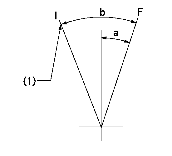
F:Full load
I:Idle
(1)Stopper bolt setting
(2)Attach the return spring to the upper hole and adjust.
----------
----------
a=30deg+-5deg b=30deg+-3deg
----------
----------
a=30deg+-5deg b=30deg+-3deg
Stop lever angle

N:Pump normal
S:Stop the pump.
----------
----------
a=32deg+-5deg b=64deg+-5deg
----------
----------
a=32deg+-5deg b=64deg+-5deg
Timing setting

(1)Pump vertical direction
(2)Position of timer's threaded hole at No 1 cylinder's beginning of injection
(3)B.T.D.C.: aa
(4)-
----------
aa=11deg
----------
a=(70deg)
----------
aa=11deg
----------
a=(70deg)
Information:
In this service manual, the Mitsubishi Diesel Engine (standard model for land use) specifications, maintenance standards and adjustment procedure as well as service procedures such as disassembly, inspection, repair and reassembly are arranged in groups for quick reference. There are separate manuals for the fuel injection pump, governor and turbocharger.A short summary of each group is given in the General Contents, and there is also a table of contents at the beginning of each group.Regarding engine operation and periodical maintenance, refer to the Operation & Maintenance Manual. For component parts and ordering of service parts, refer to the Parts Catalog. Structure and function of the engine are described in various training manuals.Methods of Indication
(1) Parts shown in illustrations and described in text are numbered to correspond with the sequence of disassembly.(2) Inspections to be conducted during disassembly are indicated in a box
in disassembled views.(3) Maintenance standards for inspection and repair are described in text where they are relevant, are also listed in Group 1 in the General Contents.(4) The sequence in which parts are to be assembled is summarized below each assembled view. Such as:
(5) The following marks are used in this manual to emphasize important safety cautions.
Indicates a highly hazardous situation which, if not avoided, can result in death or serious injury.
Indicates a potentially hazardous situation which, if not avoided, can result in death or serious injury.
Indicates a potentially hazardous situation which, if not avoided, can result in minor or moderate injury.
Indicates a potentially hazardous situation which, if not avoided, can result in property damage. Note: Indicates important information or information which is useful for engine operation or maintenance.(6) Tightening torque under wet conditions is indicated as, "[Wet]". When so indicated, apply engine oil to the threaded portion of the fastener. Unless indicated as such, the tightening torque is to be assumed in the dry condition.Terms Used in This Manual
Nominal value - Indicates the standard dimension of a part to be measured.Standard - Indicates the dimension of a part, the clearance between parts, or the standard performance. Since the value is indicated in a range needed for inspection, it is different from the design value.Limit - A part must be repaired or replaced with a new part when it reaches the limit value.Abbreviations, Standard, Etc.
* BTDC = Before Top Dead Center* ATDC = After Top Dead Center* BBDC = Before Bottom Dead Center* ABDC = After Bottom Dead Center* TIR = Total Indicated Reading* API = American Petroleum Institute* ASTM = American Society for Testing and Materials* JIS = Japanese Industrial Standards* LLC = Long Life Coolant* MIL = Military Specifications and Standards (U.S.)* MSDS = Material Safety Data Sheet* SAE = Society of Automotive Engineers (U.S.)Units of Measurement
Measurements are based on the International System of Units (SI), and their converted metric values are indicated in parentheses ( ). For metric conversion, the following rates are used.* Pressure: 1 MPa = 10.197 kgf/cm2* Torque: 1 N m = 0.10197 kgf m* Force: 1 N