Information injection-pump assembly
ZEXEL
106693-6102
1066936102
ISUZU
1156021971
1156021971
Rating:
Service parts 106693-6102 INJECTION-PUMP ASSEMBLY:
1.
_
7.
COUPLING PLATE
8.
_
9.
_
11.
Nozzle and Holder
1-15300-041-2
12.
Open Pre:MPa(Kqf/cm2)
22.1{225}

15.
NOZZLE SET
Include in #1:
106693-6102
as INJECTION-PUMP ASSEMBLY
Cross reference number
ZEXEL
106693-6102
1066936102
ISUZU
1156021971
1156021971
Zexel num
Bosch num
Firm num
Name
Calibration Data:
Adjustment conditions
Test oil
1404 Test oil ISO4113 or {SAEJ967d}
1404 Test oil ISO4113 or {SAEJ967d}
Test oil temperature
degC
40
40
45
Nozzle and nozzle holder
105780-8140
Bosch type code
EF8511/9A
Nozzle
105780-0000
Bosch type code
DN12SD12T
Nozzle holder
105780-2080
Bosch type code
EF8511/9
Opening pressure
MPa
17.2
Opening pressure
kgf/cm2
175
Injection pipe
Outer diameter - inner diameter - length (mm) mm 8-3-600
Outer diameter - inner diameter - length (mm) mm 8-3-600
Overflow valve
132424-0620
Overflow valve opening pressure
kPa
157
123
191
Overflow valve opening pressure
kgf/cm2
1.6
1.25
1.95
Tester oil delivery pressure
kPa
157
157
157
Tester oil delivery pressure
kgf/cm2
1.6
1.6
1.6
Direction of rotation (viewed from drive side)
Right R
Right R
Injection timing adjustment
Direction of rotation (viewed from drive side)
Right R
Right R
Injection order
1-4-2-6-
3-5
Pre-stroke
mm
3
2.95
3.05
Beginning of injection position
Drive side NO.1
Drive side NO.1
Difference between angles 1
Cal 1-4 deg. 60 59.5 60.5
Cal 1-4 deg. 60 59.5 60.5
Difference between angles 2
Cyl.1-2 deg. 120 119.5 120.5
Cyl.1-2 deg. 120 119.5 120.5
Difference between angles 3
Cal 1-6 deg. 180 179.5 180.5
Cal 1-6 deg. 180 179.5 180.5
Difference between angles 4
Cal 1-3 deg. 240 239.5 240.5
Cal 1-3 deg. 240 239.5 240.5
Difference between angles 5
Cal 1-5 deg. 300 299.5 300.5
Cal 1-5 deg. 300 299.5 300.5
Injection quantity adjustment
Adjusting point
A
Rack position
9.3
Pump speed
r/min
700
700
700
Average injection quantity
mm3/st.
138.5
137.5
139.5
Max. variation between cylinders
%
0
-3
3
Basic
*
Fixing the lever
*
Injection quantity adjustment_02
Adjusting point
B
Rack position
5.7+-0.5
Pump speed
r/min
225
225
225
Average injection quantity
mm3/st.
13
11
15
Max. variation between cylinders
%
0
-13
13
Fixing the rack
*
Injection quantity adjustment_03
Adjusting point
C
Rack position
13+-0.5
Pump speed
r/min
150
150
150
Average injection quantity
mm3/st.
175
175
Fixing the lever
*
Remarks
After startup boost setting
After startup boost setting
Injection quantity adjustment_04
Adjusting point
D
Rack position
R1(8.3)
Pump speed
r/min
700
700
700
Average injection quantity
mm3/st.
113.5
112.5
114.5
Max. variation between cylinders
%
0
-3
3
Fixing the lever
*
Remarks
At absolute pressure 69.8 kPa {524 mmHg}
At absolute pressure 69.8 kPa {524 mmHg}
Injection quantity adjustment_05
Adjusting point
E
Rack position
9.3+-0.5
Pump speed
r/min
1150
1150
1150
Average injection quantity
mm3/st.
142
138
146
Max. variation between cylinders
%
0
-3
3
Fixing the lever
*
Timer adjustment
Pump speed
r/min
700
Advance angle
deg.
0.3
Timer adjustment_02
Pump speed
r/min
800
Advance angle
deg.
0.9
0.1
0.9
Timer adjustment_03
Pump speed
r/min
900
Advance angle
deg.
1
0.5
1.5
Timer adjustment_04
Pump speed
r/min
1150
Advance angle
deg.
3
2.5
3.5
Remarks
Finish
Finish
Test data Ex:
Governor adjustment
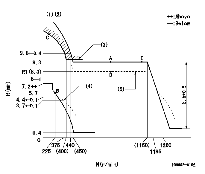
N:Pump speed
R:Rack position (mm)
(1)Tolerance for racks not indicated: +-0.05mm.
(2)Attach the load lever return spring to the upper hole and adjust the governor.
(3)Excess fuel setting for starting: SXL (N = N1)
(4)Damper spring setting
(5)Aneroid compensator absolute pressure: P1
----------
SXL=9.4+0.2mm N1=430r/min P1=69.8+-0.7kPa(524+-5mmHg)
----------
----------
SXL=9.4+0.2mm N1=430r/min P1=69.8+-0.7kPa(524+-5mmHg)
----------
Speed control lever angle

F:Full speed
----------
----------
a=6deg+-5deg
----------
----------
a=6deg+-5deg
0000000901

F:Full load
I:Idle
(1)Stopper bolt setting
(2)Attach the load lever return spring to the upper hole and adjust the governor.
----------
----------
a=30deg+-5deg b=31deg+-3deg
----------
----------
a=30deg+-5deg b=31deg+-3deg
Stop lever angle

N:Pump normal
S:Stop the pump.
----------
----------
a=32deg+-5deg b=64deg+-5deg
----------
----------
a=32deg+-5deg b=64deg+-5deg
0000001501 ACS
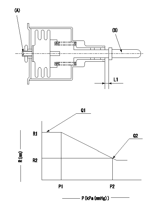
(A) Set screw
(B) Push rod 1
1. Aneroid compensator unit adjustment
(1)Screw in (A) to obtain L1.
2. Adjustment following governor installation
(1)Set the speed of the pump to N1 r/min and fix the control lever at the full set position.
(2)Screw in the aneroid compensator to obtain the performance shown in the graph above.
----------
N1=700r/min L1=0.6~0.9mm
----------
R1=9.3mm R2=R1(8.3)mm P1=(89.8)kPa((674)mmHg) P2=69.8+-0.7kPa(524+-5mmHg) Q1=138.5+-1cm3/1000st Q2=113.5+-1cm3/1000st
----------
N1=700r/min L1=0.6~0.9mm
----------
R1=9.3mm R2=R1(8.3)mm P1=(89.8)kPa((674)mmHg) P2=69.8+-0.7kPa(524+-5mmHg) Q1=138.5+-1cm3/1000st Q2=113.5+-1cm3/1000st
Timing setting

(1)Pump vertical direction
(2)Position of timer's threaded hole at No 1 cylinder's beginning of injection
(3)B.T.D.C.: aa
(4)-
----------
aa=16deg
----------
a=(70deg)
----------
aa=16deg
----------
a=(70deg)
Information:
Adjustment of valve clearanceFuel System Bleeding
(1) Loosen the air vent plug of the fuel filter. (approx. 1.5 turns)(2) Move the priming pump for the filter up and down.(3) When fuel flowing from the vent hole no longer contains air bubbles, tighten the air vent plug.
Fuel system bleedingInspection and Adjustment of No-Load Minimum (Low Idling) Speed and Maximum Speed
(a) The following adjustments were inspected and set for each engine on the test bench at the factory, and the set bolts are sealed. These settings should be checked and adjusted only at our designated service shop.(b) After the governor parts are adjusted, all external stoppers must be sealed in the same way as when adjustments were made at the factory.(c) Whether the seals are intact or not has important bearing on the validity of claims under warranty. Be sure to seal all the specified sections.(d) When inspecting or adjusting, be ready to operate the engine stop lever manually in case the engine overruns (engine operation at extremely high speed).
Prior to inspection and adjustment, conduct a warm-up operation until the coolant and oil temperatures rise above 70 °C [158 °F].(1) Starting the engine(a) Pull the speed control lever toward the HIGH SPEED side, and operate the starter switch.(b) The engine ignites when the rotation speed reaches approximately 150 min-1, and the engine speed rises. Operate the speed control lever to maintain the engine speed between 800 and 1000 min-1.(c) After the engine speed stabilizes, return the speed control lever to the low idling position.
Inspection and adjustment of no-load minimum (low idling) speed and maximum speed(2) Low idling setting (no-load minimum rotation speed setting)Hold the speed control lever at the position of no-load minimum rotation speed, then secure the lever in that position using the idling adjustment screw.
If there is speed range which causes dangerous torsional vibration, avoid setting the engine speed in that range.
(3) Governor setting (maximum rotation speed setting)(a) Keep the speed control lever at the position of the specified maximum rotation speed.(b) With the speed control lever held in that position, adjust and set the governor set bolt (maximum rotation speed set screw) to the specified rotation speed).Inspection of V-Belt Tension
(1) Press the V-belt at a midpoint between the alternator and crankshaft pulley to check the mount of belt deflection.
Inspection of V-belt tension(2) If the amount of belt deflection does not conform to the standard value, loosen the adjusting bolt and move the alternator to adjust the belt tension.Engine Break-in Operation
When the engine is overhauled, it should be mounted on a dynamometer and operated for break-in and inspection.Starting Up
(1) Before starting the engine, check the levels of coolant, engine oil and fuel, and bleed the fuel and cooling system.(2) With the fuel supply cut off, operate the starter and crank the engine for about 15 seconds to circulate engine oil.(3) Move the speed control lever slightly in the direction for increased fuel (do not move it to "full injection" position), then turn the starter switch key to the [START]