Information injection-pump assembly
ZEXEL
106693-6080
1066936080
ISUZU
1156027460
1156027460
Rating:
Service parts 106693-6080 INJECTION-PUMP ASSEMBLY:
1.
_
7.
COUPLING PLATE
8.
_
9.
_
11.
Nozzle and Holder
1-15300-218-1
12.
Open Pre:MPa(Kqf/cm2)
17.7{180}/22.1{225}
15.
NOZZLE SET
Include in #1:
106693-6080
as INJECTION-PUMP ASSEMBLY
Cross reference number
ZEXEL
106693-6080
1066936080
ISUZU
1156027460
1156027460
Zexel num
Bosch num
Firm num
Name
Calibration Data:
Adjustment conditions
Test oil
1404 Test oil ISO4113 or {SAEJ967d}
1404 Test oil ISO4113 or {SAEJ967d}
Test oil temperature
degC
40
40
45
Nozzle and nozzle holder
105780-8140
Bosch type code
EF8511/9A
Nozzle
105780-0000
Bosch type code
DN12SD12T
Nozzle holder
105780-2080
Bosch type code
EF8511/9
Opening pressure
MPa
17.2
Opening pressure
kgf/cm2
175
Injection pipe
Outer diameter - inner diameter - length (mm) mm 8-3-600
Outer diameter - inner diameter - length (mm) mm 8-3-600
Overflow valve
134424-1920
Overflow valve opening pressure
kPa
127
107
147
Overflow valve opening pressure
kgf/cm2
1.3
1.1
1.5
Tester oil delivery pressure
kPa
157
157
157
Tester oil delivery pressure
kgf/cm2
1.6
1.6
1.6
Direction of rotation (viewed from drive side)
Left L
Left L
Injection timing adjustment
Direction of rotation (viewed from drive side)
Left L
Left L
Injection order
1-5-3-6-
2-4
Pre-stroke
mm
3.7
3.67
3.73
Beginning of injection position
Governor side NO.1
Governor side NO.1
Difference between angles 1
Cal 1-5 deg. 60 59.75 60.25
Cal 1-5 deg. 60 59.75 60.25
Difference between angles 2
Cal 1-3 deg. 120 119.75 120.25
Cal 1-3 deg. 120 119.75 120.25
Difference between angles 3
Cal 1-6 deg. 180 179.75 180.25
Cal 1-6 deg. 180 179.75 180.25
Difference between angles 4
Cyl.1-2 deg. 240 239.75 240.25
Cyl.1-2 deg. 240 239.75 240.25
Difference between angles 5
Cal 1-4 deg. 300 299.75 300.25
Cal 1-4 deg. 300 299.75 300.25
Injection quantity adjustment
Adjusting point
A
Rack position
11.2
Pump speed
r/min
700
700
700
Average injection quantity
mm3/st.
162.2
160.2
164.2
Max. variation between cylinders
%
0
-3
3
Basic
*
Fixing the lever
*
Boost pressure
kPa
41.3
41.3
Boost pressure
mmHg
310
310
Injection quantity adjustment_02
Adjusting point
E
Rack position
5.5+-0.5
Pump speed
r/min
240
240
240
Average injection quantity
mm3/st.
11.6
8.4
14.8
Max. variation between cylinders
%
0
-13
13
Fixing the rack
*
Boost pressure
kPa
0
0
0
Boost pressure
mmHg
0
0
0
Boost compensator adjustment
Pump speed
r/min
500
500
500
Rack position
8.2
Boost pressure
kPa
10
8.7
11.3
Boost pressure
mmHg
75
65
85
Boost compensator adjustment_02
Pump speed
r/min
500
500
500
Rack position
9.3
Boost pressure
kPa
14
11.3
16.7
Boost pressure
mmHg
105
85
125
Boost compensator adjustment_03
Pump speed
r/min
500
500
500
Rack position
11.2
Boost pressure
kPa
28
28
28
Boost pressure
mmHg
210
210
210
Test data Ex:
Governor adjustment
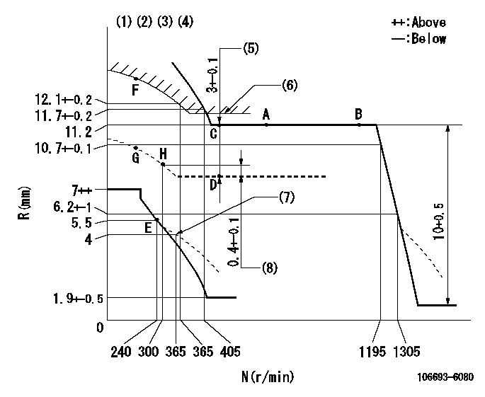
N:Pump speed
R:Rack position (mm)
(1)Lever ratio: RT
(2)Target shim dimension: TH
(3)Tolerance for racks not indicated: +-0.05mm.
(4)Supplied with torque spring not set.
(5)Boost compensator stroke
(6)Excess fuel setting for starting: SXL
(7)Damper spring setting
(8)Rack difference from N = N1
----------
RT=1 TH=2.7mm SXL=11.6+-0.1mm N1=500r/min
----------
----------
RT=1 TH=2.7mm SXL=11.6+-0.1mm N1=500r/min
----------
Timer adjustment

(1)Adjusting range
(2)Step response time
(N): Speed of the pump
(L): Load
(theta) Advance angle
(Srd1) Step response time 1
(Srd2) Step response time 2
1. Adjusting conditions for the variable timer
(1)Adjust the clearance between the pickup and the protrusion to L.
----------
L=1-0.2mm N2=800r/min C2=(5.5)deg t1=2--sec. t2=2--sec.
----------
N1=800++r/min P1=0kPa(0kgf/cm2) P2=392kPa(4kgf/cm2) C1=5.5+-3deg R01=0/4load R02=4/4load
----------
L=1-0.2mm N2=800r/min C2=(5.5)deg t1=2--sec. t2=2--sec.
----------
N1=800++r/min P1=0kPa(0kgf/cm2) P2=392kPa(4kgf/cm2) C1=5.5+-3deg R01=0/4load R02=4/4load
Speed control lever angle

F:Full speed
----------
----------
a=6deg+-5deg
----------
----------
a=6deg+-5deg
0000000901

F:Full load
I:Idle
(1)Use the hole at R = aa
(2)Stopper bolt setting
----------
aa=35mm
----------
a=15deg+-5deg b=34.5deg+-3deg
----------
aa=35mm
----------
a=15deg+-5deg b=34.5deg+-3deg
Stop lever angle

N:Pump normal
S:Stop the pump.
----------
----------
a=(37deg)+-5deg b=73deg+-5deg
----------
----------
a=(37deg)+-5deg b=73deg+-5deg
0000001501 RACK SENSOR

(VR) measurement voltage
(I) Part number of the control unit
(G) Apply red paint.
(H): End surface of the pump
1. Rack sensor adjustment (-0620)
(1)Fix the speed control lever at the full position
(2)Set the speed to N1 r/min.
(If the boost compensator is provided, apply boost pressure.)
(3)Adjust the bobbin (A) so that the rack sensor's output voltage is VR+-0.01.
(4)At that time, rack position must be Ra.
(5)Apply G at two places.
Connecting part between the joint (B) and the nut (F)
Connecting part between the joint (B) and the end surface of the pump (H)
----------
N1=700r/min Ra=11.2mm
----------
----------
N1=700r/min Ra=11.2mm
----------
Timing setting

(1)Pump vertical direction
(2)Position of timer's threaded hole at No 1 cylinder's beginning of injection
(3)B.T.D.C.: aa
(4)-
----------
aa=10deg
----------
a=(40deg)
----------
aa=10deg
----------
a=(40deg)
Information:
(a)When regrinding journals of the crankshaft, be sure to refinish all journals to the same dimension.(b)Finish the fillet radius to R3 mm [0.1181 in.].
Crankshaft fillet finishing dimension (2)Inspection of Oil Seal Contact Surface
Check the oil seal contact surface of the crankshaft back-end, and, if the crankshaft face has been excessively worn by the oil seal, replace the oil seal and oil sleeve with replacement parts.
Inspection of oil seal contact surface(1) Installation of oil seal sleeveTo install the oil seal sleeve, coat the inner surface of the sleeve with oil, and use the crankshaft sleeve installer for driving the sleeve into place.
Be careful not to dent or scratch the outer surface of the oil seal sleeve.
Inspection of oil seal sleeveWhen the oil seal slinger becomes worn after engine operation, remove the oil seal sleeve by following the procedure below, and replace it with a replacement oil seal assembly (oil seal and oil seal sleeve).
Inspection of oil seal contact surface(2) Removal of oil seal sleeveAt three locations on the sleeve end face, hold a chisel at a right angle to the sleeve and strike with a hammer, and remove the sleeve when it becomes loose.If this method does not allow the removal of the sleeve, hold the chisel in the axial direction and lightly tap to expand and loosen the sleeve.
Be careful not to damage the crankshaft with the chisel when removing the oil seal sleeve.
Removal of oil seal sleeveMeasurement of Crankshaft Deflection
Support the crankshaft on its front and rear journals in V-blocks, and measure the runout at the center journal with a dial gage. Compare the amount of runout with the standard. If the runout is small, correct by grinding. If the runout is large, straighten with a press.If the runout exceeds the limit significantly, replace the crankshaft.
Measurement of crankshaft deflectionRemoval of Crankshaft Gear
Use the gear puller to remove the crankshaft gear. Do not remove the crankshaft gear unless the crankshaft or gear is replaced.
Removal of crankshaft gearInstallation of Crankshaft Gear
(1) Heat the gear to a temperature of 100 to 150 °C [212 to 302 °F].(2) Install the key to the crankshaft.(3) Align the gear with key and insert the gear fully.
Installation of crankshaft gearMeasurement of Cylinder Bore
(1) Using a cylinder gage, measure the cylinder bore and cylindricity. If the limit value is exceeded even at one place, bore all cylinders and replace the pistons and piston rings with oversize pistons and piston rings. Measure at three locations each in directions A and B shown in the diagram.
Measurement of inside diameter of cylinder(2) Boring of cylinders(a) Since there are two piston oversizes (0.25 mm [0.0098 in.] and 0.50 mm [0.0197 in.] oversize) as indicated above, determine the appropriate piston size to be used based on the largest cylinder bore diameter.(b) Measure the outside diameter of the piston to be used. The piston diameter measuring points are shown in the diagram.(c) Based on the measurements of the piston outside diameter, calculate the finishing dimension to be achieved by boring.A: Piston