Information injection-pump assembly
ZEXEL
106693-6070
1066936070
ISUZU
1156027440
1156027440

Rating:
Service parts 106693-6070 INJECTION-PUMP ASSEMBLY:
1.
_
7.
COUPLING PLATE
8.
_
9.
_
11.
Nozzle and Holder
1-15300-218-1
12.
Open Pre:MPa(Kqf/cm2)
17.7{180}/22.1{225}
15.
NOZZLE SET
Include in #1:
106693-6070
as INJECTION-PUMP ASSEMBLY
Cross reference number
ZEXEL
106693-6070
1066936070
ISUZU
1156027440
1156027440
Zexel num
Bosch num
Firm num
Name
Calibration Data:
Adjustment conditions
Test oil
1404 Test oil ISO4113 or {SAEJ967d}
1404 Test oil ISO4113 or {SAEJ967d}
Test oil temperature
degC
40
40
45
Nozzle and nozzle holder
105780-8140
Bosch type code
EF8511/9A
Nozzle
105780-0000
Bosch type code
DN12SD12T
Nozzle holder
105780-2080
Bosch type code
EF8511/9
Opening pressure
MPa
17.2
Opening pressure
kgf/cm2
175
Injection pipe
Outer diameter - inner diameter - length (mm) mm 8-3-600
Outer diameter - inner diameter - length (mm) mm 8-3-600
Overflow valve
134424-1920
Overflow valve opening pressure
kPa
127
107
147
Overflow valve opening pressure
kgf/cm2
1.3
1.1
1.5
Tester oil delivery pressure
kPa
157
157
157
Tester oil delivery pressure
kgf/cm2
1.6
1.6
1.6
Direction of rotation (viewed from drive side)
Left L
Left L
Injection timing adjustment
Direction of rotation (viewed from drive side)
Left L
Left L
Injection order
1-5-3-6-
2-4
Pre-stroke
mm
3.7
3.67
3.73
Beginning of injection position
Governor side NO.1
Governor side NO.1
Difference between angles 1
Cal 1-5 deg. 60 59.75 60.25
Cal 1-5 deg. 60 59.75 60.25
Difference between angles 2
Cal 1-3 deg. 120 119.75 120.25
Cal 1-3 deg. 120 119.75 120.25
Difference between angles 3
Cal 1-6 deg. 180 179.75 180.25
Cal 1-6 deg. 180 179.75 180.25
Difference between angles 4
Cyl.1-2 deg. 240 239.75 240.25
Cyl.1-2 deg. 240 239.75 240.25
Difference between angles 5
Cal 1-4 deg. 300 299.75 300.25
Cal 1-4 deg. 300 299.75 300.25
Injection quantity adjustment
Adjusting point
A
Rack position
9
Pump speed
r/min
600
600
600
Average injection quantity
mm3/st.
160.4
158.4
162.4
Max. variation between cylinders
%
0
-3
3
Basic
*
Fixing the lever
*
Boost pressure
kPa
48
48
Boost pressure
mmHg
360
360
Injection quantity adjustment_02
Adjusting point
B
Rack position
8.9
Pump speed
r/min
1100
1100
1100
Average injection quantity
mm3/st.
162.3
160.3
164.3
Fixing the lever
*
Boost pressure
kPa
48
48
Boost pressure
mmHg
360
360
Injection quantity adjustment_03
Adjusting point
D
Rack position
4.9+-0.5
Pump speed
r/min
235
235
235
Average injection quantity
mm3/st.
12.5
9.3
15.7
Max. variation between cylinders
%
0
-13
13
Fixing the rack
*
Boost pressure
kPa
0
0
0
Boost pressure
mmHg
0
0
0
Boost compensator adjustment
Pump speed
r/min
600
600
600
Rack position
6.9
Boost pressure
kPa
10
8.7
11.3
Boost pressure
mmHg
75
65
85
Boost compensator adjustment_02
Pump speed
r/min
600
600
600
Rack position
7.9
Boost pressure
kPa
17.3
14.6
20
Boost pressure
mmHg
130
110
150
Boost compensator adjustment_03
Pump speed
r/min
600
600
600
Rack position
8.5
Boost pressure
kPa
23.3
20
26.6
Boost pressure
mmHg
175
150
200
Boost compensator adjustment_04
Pump speed
r/min
600
600
600
Rack position
9
Boost pressure
kPa
34.7
34.7
34.7
Boost pressure
mmHg
260
260
260
Test data Ex:
Governor adjustment
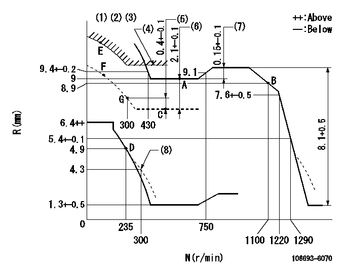
N:Pump speed
R:Rack position (mm)
(1)Lever ratio: RT
(2)Target shim dimension: TH
(3)Tolerance for racks not indicated: +-0.05mm.
(4)Excess fuel setting for starting: SXL
(5)Rack difference from N = N1
(6)Boost compensator stroke
(7)Rack difference between N = N2 and N = N3
(8)Damper spring setting
----------
RT=0.8 TH=2.8mm SXL=9.6+-0.1mm N1=500r/min N2=900r/min N3=600r/min
----------
----------
RT=0.8 TH=2.8mm SXL=9.6+-0.1mm N1=500r/min N2=900r/min N3=600r/min
----------
Timer adjustment

(1)Adjusting range
(2)Step response time
(N): Speed of the pump
(L): Load
(theta) Advance angle
(Srd1) Step response time 1
(Srd2) Step response time 2
1. Adjusting conditions for the variable timer
(1)Adjust the clearance between the pickup and the protrusion to L.
----------
L=1-0.2mm N2=800r/min C2=(5.5)deg t1=2--sec. t2=2--sec.
----------
N1=800++r/min P1=0kPa(0kgf/cm2) P2=392kPa(4kgf/cm2) C1=5.5+-0.3deg R01=0/4load R02=4/4load
----------
L=1-0.2mm N2=800r/min C2=(5.5)deg t1=2--sec. t2=2--sec.
----------
N1=800++r/min P1=0kPa(0kgf/cm2) P2=392kPa(4kgf/cm2) C1=5.5+-0.3deg R01=0/4load R02=4/4load
Speed control lever angle

F:Full speed
----------
----------
a=5deg+-5deg
----------
----------
a=5deg+-5deg
0000000901

F:Full load
I:Idle
(1)Stopper bolt setting
(2)Use the hole at R = aa
----------
aa=35mm
----------
a=15deg+-5deg b=41deg+-3deg
----------
aa=35mm
----------
a=15deg+-5deg b=41deg+-3deg
Stop lever angle

N:Pump normal
S:Stop the pump.
----------
----------
a=37deg+-5deg b=73deg+-5deg
----------
----------
a=37deg+-5deg b=73deg+-5deg
0000001501 RACK SENSOR

(VR) measurement voltage
(I) Part number of the control unit
(G) Apply red paint.
(H): End surface of the pump
1. Rack sensor adjustment (-0620)
(1)Fix the speed control lever at the full position
(2)Set the speed to N1 r/min.
(If the boost compensator is provided, apply boost pressure.)
(3)Adjust the bobbin (A) so that the rack sensor's output voltage is VR+-0.01.
(4)At that time, rack position must be Ra.
(5)Apply G at two places.
Connecting part between the joint (B) and the nut (F)
Connecting part between the joint (B) and the end surface of the pump (H)
----------
N1=900r/min Ra=9.15mm
----------
----------
N1=900r/min Ra=9.15mm
----------
Timing setting

(1)Pump vertical direction
(2)Position of timer's threaded hole at No 1 cylinder's beginning of injection
(3)B.T.D.C.: aa
(4)-
----------
aa=10deg
----------
a=(40deg)
----------
aa=10deg
----------
a=(40deg)
Information:
Determination Of Overhaul Timing
Generally, the engine needs an overhaul when the compression pressure of the engine becomes low, and the amounts of engine oil consumption and blow-by gas increase.Reduced power output, increased fuel consumption, low oil pressure, difficult in starting, and increased operating noise are also signs that suggest the need for an overhaul; however, since these problems can be caused by various factors, they do not serve as reliable criteria for determining the need for an overhaul.Reduced compression pressure manifests a variety of symptoms, thus making it difficult to accurately determine when the engine needs an overhaul. The following shows typical problems caused by reduced compression pressure.(1) Decreased output power(2) Increased fuel consumption(3) Increased engine oil consumption(4) Increased blow-by gas from breather due to leakage of combustion gas through worn cylinder liners and piston rings(5) Increased gas leakage due to poor seating of inlet and exhaust valves(6) Difficulty in starting(7) Increased noise from engine parts(8) Abnormal exhaust color after warm-up operationThe engine can exhibit these conditions in various combinations.Some of these problems are directly caused by worn engine parts, while others are not.Phenomena described in (2) and (6) can also result from improper injection volume, incorrect fuel injection timing, worn plungers, defective nozzles, and faulty conditions of electrical devices such as battery, starter and alternator.The most valid reason to overhaul an engine is a decrease in the compression pressure due to worn cylinder liners and pistons, as described in (4), and once this is determined, other symptoms should be taken into consideration in order to make the final judgement of whether the engine needs an overhaul.Measurement of Compression Pressure
Preparation For Inspection
Check the following before inspection.(1) Make sure that the engine oil, air cleaner, starter, battery, etc. are in normal operating condition.
Measurement of compression pressureInspection
(1) Move the control lever to the Stop position.(2) Remove the glow plugs from all cylinders, and attach the gage adapter and compression gage to the cylinder to be tested. (3) Crank the engine with the starter, and read the compression gage indication when the indication stabilizes.(4) If the measured compression pressure is lower than the limit, consider overhauling the engine.
(a) Measure the compression pressure in all cylinders.(b) As compression pressure varies with the engine speed, measure the engine speed at the same time.
Measure the compression pressure while the engine is running at 150 to 200 min-1. The oil and coolant temperatures should be between 20 and 30 °C [68 and 86°F].
(a) Measure the compression pressure at regular intervals to keep the record of changes in compression pressure.(b) Compression pressure will be slightly higher when the engine is new or immediately after an overhaul due to tight clearances of piston rings and valve seats, but it decreases to the standard level after the parts break in.