Information injection-pump assembly
ZEXEL
106693-1980
1066931980
ISUZU
1156026160
1156026160
Rating:
Service parts 106693-1980 INJECTION-PUMP ASSEMBLY:
1.
_
7.
COUPLING PLATE
8.
_
9.
_
11.
Nozzle and Holder
1-15300-259-1
12.
Open Pre:MPa(Kqf/cm2)
15.7{160}/17.7{180}
15.
NOZZLE SET
Include in #1:
106693-1980
as INJECTION-PUMP ASSEMBLY
Cross reference number
ZEXEL
106693-1980
1066931980
ISUZU
1156026160
1156026160
Zexel num
Bosch num
Firm num
Name
Calibration Data:
Adjustment conditions
Test oil
1404 Test oil ISO4113 or {SAEJ967d}
1404 Test oil ISO4113 or {SAEJ967d}
Test oil temperature
degC
40
40
45
Nozzle and nozzle holder
105780-8140
Bosch type code
EF8511/9A
Nozzle
105780-0000
Bosch type code
DN12SD12T
Nozzle holder
105780-2080
Bosch type code
EF8511/9
Opening pressure
MPa
17.2
Opening pressure
kgf/cm2
175
Injection pipe
Outer diameter - inner diameter - length (mm) mm 8-3-600
Outer diameter - inner diameter - length (mm) mm 8-3-600
Overflow valve
134424-1920
Overflow valve opening pressure
kPa
127
107
147
Overflow valve opening pressure
kgf/cm2
1.3
1.1
1.5
Tester oil delivery pressure
kPa
157
157
157
Tester oil delivery pressure
kgf/cm2
1.6
1.6
1.6
Direction of rotation (viewed from drive side)
Right R
Right R
Injection timing adjustment
Direction of rotation (viewed from drive side)
Right R
Right R
Injection order
1-4-2-6-
3-5
Pre-stroke
mm
3
2.97
3.03
Beginning of injection position
Drive side NO.1
Drive side NO.1
Difference between angles 1
Cal 1-4 deg. 60 59.75 60.25
Cal 1-4 deg. 60 59.75 60.25
Difference between angles 2
Cyl.1-2 deg. 120 119.75 120.25
Cyl.1-2 deg. 120 119.75 120.25
Difference between angles 3
Cal 1-6 deg. 180 179.75 180.25
Cal 1-6 deg. 180 179.75 180.25
Difference between angles 4
Cal 1-3 deg. 240 239.75 240.25
Cal 1-3 deg. 240 239.75 240.25
Difference between angles 5
Cal 1-5 deg. 300 299.75 300.25
Cal 1-5 deg. 300 299.75 300.25
Injection quantity adjustment
Adjusting point
A
Rack position
7.5
Pump speed
r/min
700
700
700
Average injection quantity
mm3/st.
117
115
119
Max. variation between cylinders
%
0
-3
3
Basic
*
Fixing the lever
*
Injection quantity adjustment_02
Adjusting point
B
Rack position
8.3
Pump speed
r/min
1125
1125
1125
Average injection quantity
mm3/st.
139.1
137.1
141.1
Max. variation between cylinders
%
0
-4
4
Fixing the lever
*
Injection quantity adjustment_03
Adjusting point
-
Rack position
4.5+-0.5
Pump speed
r/min
225
225
225
Average injection quantity
mm3/st.
8
4.8
11.2
Max. variation between cylinders
%
0
-13
13
Fixing the rack
*
Remarks
Adjust only variation between cylinders; adjust governor according to governor specifications.
Adjust only variation between cylinders; adjust governor according to governor specifications.
Injection quantity adjustment_04
Adjusting point
D
Rack position
(9.8)+-0
.1
Pump speed
r/min
100
100
100
Average injection quantity
mm3/st.
122.5
112.5
132.5
Fixing the lever
*
Remarks
After startup boost setting
After startup boost setting
Timer adjustment
Pump speed
r/min
950--
Advance angle
deg.
0
0
0
Load
3/4
Remarks
Start
Start
Timer adjustment_02
Pump speed
r/min
900
Advance angle
deg.
0.3
Load
3/4
Timer adjustment_03
Pump speed
r/min
1150
Advance angle
deg.
5.5
5
6
Load
4/4
Remarks
Finish
Finish
Test data Ex:
Governor adjustment
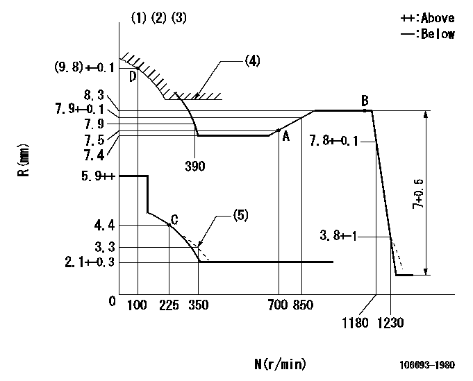
N:Pump speed
R:Rack position (mm)
(1)Lever ratio: RT
(2)Target shim dimension: TH
(3)Tolerance for racks not indicated: +-0.05mm.
(4)Excess fuel setting for starting: SXL
(5)Damper spring setting
----------
RT=0.8 TH=2.9mm SXL=8.6+-0.1mm
----------
----------
RT=0.8 TH=2.9mm SXL=8.6+-0.1mm
----------
Speed control lever angle

F:Full speed
----------
----------
a=4.5deg+-5deg
----------
----------
a=4.5deg+-5deg
0000000901
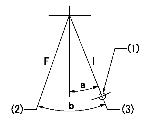
F:Full load
I:Idle
(1)Use the hole at R = aa
(2)Attach the return spring to the bottom hole and adjust.
(3)Stopper bolt setting
----------
aa=73mm
----------
a=15deg+-5deg b=28.5deg+-3deg
----------
aa=73mm
----------
a=15deg+-5deg b=28.5deg+-3deg
Stop lever angle

N:Pump normal
S:Stop the pump.
----------
----------
a=52deg+-5deg b=64deg+-5deg
----------
----------
a=52deg+-5deg b=64deg+-5deg
0000001501 GOVERNOR TORQUE CONTROL

Dr:Torque control stroke
(A): Without torque control spring capsule
1. Adjustment procedures
(1)Procedure is the same as that for the RFD (former type), except that the positive torque control stroke must be determined at the full lever setting.
2. Procedures for adjustment
(1)Remove the torque control spring capsule.
(2)Operate the pump at approximately N1. (End of idling spring operation < N1.)
(3)Tilt the lever to the full side.
(4)Set so that R = RF.
(5)Increase the speed by pushing in the screw (attached to the bracket on the rear of the tension lever) through the adjusting window.
(6)Adjust so that the torque control stroke Dr1 can be obtained.
(7)Align N2 and N3 with the torque control spring capsule.
3. Final confirmation
(1)After final confirmation, temporarily set the load lever to N = N1, R = idling position.
(2)From this condition, increase speed to N = N4.
(3)Confirm that positive torque control stroke is Dr2.
----------
N1=500r/min N2=- N3=- N4=1100r/min RF=7.4mm Dr1=0.9mm Dr2=0+0.3mm
----------
----------
N1=500r/min N2=- N3=- N4=1100r/min RF=7.4mm Dr1=0.9mm Dr2=0+0.3mm
----------
Timing setting

(1)Pump vertical direction
(2)Position of timer's threaded hole at No 1 cylinder's beginning of injection
(3)B.T.D.C.: aa
(4)-
----------
aa=13deg
----------
a=(70deg)
----------
aa=13deg
----------
a=(70deg)
Information:
Overview of Lubrication System
Flow of oilOil Pump, Relief Valve, and Oil Pressure Switch
Disassembly
Removal sequence and points to check on oil pump(1) Oil filter(2) Oil pump(3) Gasket(4) Oil pump cover(5) Inner rotor(6) Outer rotor (the inner and outer rotors from a rotor assembly)(7) O-ring(8) Oil pump body(9) Relief valve(10) Oil pressure switch Key Points For Disassembly(1) Oil Pump
Remove the oil pump (parts (3) through (8) in the above illustration) as an assembly.
Removing oil pump(2) Oil Pressure Switch
Remove the switch using the Oil Pressure Switch Socket Wrench (MD998054).
Removing oil pressure switchInspection and Repair
(1) Oil Pump
(a) Using a thickness gauge, measure the clearance between the outer rotor and pump body. If the measurement exceeds the limit, replace the rotor assembly.Unit: mm (in.)
Measuring outer rotor-to-pump body clearance(b) Using a thickness gauge, measure the clearance between the outer rotor and the inner rotor. If the measurement exceeds the limit, replace the rotor assembly.Unit: mm (in.)
Measuring outer rotor-to-inner rotor clearance(c) Using a thickness edge and a thickness gauge, measure the clearance between the rotors and pump cover. If the measurement exceeds the limit, replace either the rotors or the pump body.Unit: mm (in.)
Measuring clearance between rotors and pump cover(2) Oil Pressure Switch
(a) Connect a tester (set to the ohm range) between the terminal and body of the oil pressure switch. There should be no continuity. If there is continuity, the switch is faulty and should be replaced.
Inspecting oil pressure switch(b) Insert a thin rod into the oil hole in the switch body. When the rod is then pushed in gently, there should be continuity between the switch body and terminal. If there is no continuity, the switch is faulty and should be replaced.(c) apply an air pressure of 49 kPa {0.5 kgf/cm2) (7.1 psi) to the switch through the oil hole. If there is continuity, the switch is normal. Simultaneously, check for air leakage. Any air leakage means that the diaphragm is broken and, therefore, the switch should be replaced.
Inspecting oil pressure switchAssembly
Point to note during reassembly of oil pumpPerform assembly by following the disassembly sequence in reverse: Key Points For Reassembly
Oil Pressure Switch
(a) Install the switch using the Oil Pressure Switch Socket Wrench (MD998054).(b) Before installation, apply sealant to the threads of the switch. (Use either Hermeseal H1 or ThreeBond 1104).
Installing Oil Pressure Switch
(a) Avoid applying sealant excessively to prevent it from reaching the end of the threads.(b Never tighten the switch to a torque exceeding specification.