Information injection-pump assembly
BOSCH
9 400 617 917
9400617917
ZEXEL
106693-1930
1066931930
Rating:
Service parts 106693-1930 INJECTION-PUMP ASSEMBLY:
1.
_
7.
COUPLING PLATE
8.
_
9.
_
11.
Nozzle and Holder
1-15300-197-1
12.
Open Pre:MPa(Kqf/cm2)
22.1{225}
15.
NOZZLE SET
Include in #1:
106693-1930
as INJECTION-PUMP ASSEMBLY
Cross reference number
BOSCH
9 400 617 917
9400617917
ZEXEL
106693-1930
1066931930
Zexel num
Bosch num
Firm num
Name
106693-1930
9 400 617 917
INJECTION-PUMP ASSEMBLY
6SD1-M * 14CA PE6P,6PD PE
6SD1-M * 14CA PE6P,6PD PE
106693-1930
9 400 617 917
1156024330 ISUZU
INJECTION-PUMP ASSEMBLY
6SD1-M * 14CA PE6P,6PD PE
6SD1-M * 14CA PE6P,6PD PE
Calibration Data:
Adjustment conditions
Test oil
1404 Test oil ISO4113 or {SAEJ967d}
1404 Test oil ISO4113 or {SAEJ967d}
Test oil temperature
degC
40
40
45
Nozzle and nozzle holder
105780-8140
Bosch type code
EF8511/9A
Nozzle
105780-0000
Bosch type code
DN12SD12T
Nozzle holder
105780-2080
Bosch type code
EF8511/9
Opening pressure
MPa
17.2
Opening pressure
kgf/cm2
175
Injection pipe
Outer diameter - inner diameter - length (mm) mm 8-3-600
Outer diameter - inner diameter - length (mm) mm 8-3-600
Overflow valve
134424-1920
Overflow valve opening pressure
kPa
127
107
147
Overflow valve opening pressure
kgf/cm2
1.3
1.1
1.5
Tester oil delivery pressure
kPa
157
157
157
Tester oil delivery pressure
kgf/cm2
1.6
1.6
1.6
Direction of rotation (viewed from drive side)
Left L
Left L
Injection timing adjustment
Direction of rotation (viewed from drive side)
Left L
Left L
Injection order
1-5-3-6-
2-4
Pre-stroke
mm
3.5
3.47
3.53
Beginning of injection position
Governor side NO.1
Governor side NO.1
Difference between angles 1
Cal 1-5 deg. 60 59.75 60.25
Cal 1-5 deg. 60 59.75 60.25
Difference between angles 2
Cal 1-3 deg. 120 119.75 120.25
Cal 1-3 deg. 120 119.75 120.25
Difference between angles 3
Cal 1-6 deg. 180 179.75 180.25
Cal 1-6 deg. 180 179.75 180.25
Difference between angles 4
Cyl.1-2 deg. 240 239.75 240.25
Cyl.1-2 deg. 240 239.75 240.25
Difference between angles 5
Cal 1-4 deg. 300 299.75 300.25
Cal 1-4 deg. 300 299.75 300.25
Injection quantity adjustment
Adjusting point
A
Rack position
7.5
Pump speed
r/min
1150
1150
1150
Average injection quantity
mm3/st.
106.8
104.8
108.8
Max. variation between cylinders
%
0
-3
3
Basic
*
Fixing the lever
*
Injection quantity adjustment_02
Adjusting point
B
Rack position
4.9+-0.5
Pump speed
r/min
250
250
250
Average injection quantity
mm3/st.
10.8
7.6
14
Max. variation between cylinders
%
0
-13
13
Fixing the rack
*
Injection quantity adjustment_03
Adjusting point
C
Rack position
-
Pump speed
r/min
100
100
100
Average injection quantity
mm3/st.
99
94
104
Fixing the lever
*
Rack limit
*
Timer adjustment
Pump speed
r/min
550--
Advance angle
deg.
0
0
0
Remarks
Start
Start
Timer adjustment_02
Pump speed
r/min
500
Advance angle
deg.
0.5
Timer adjustment_03
Pump speed
r/min
1000
Advance angle
deg.
6
5.5
6.5
Remarks
Finish
Finish
Test data Ex:
Governor adjustment
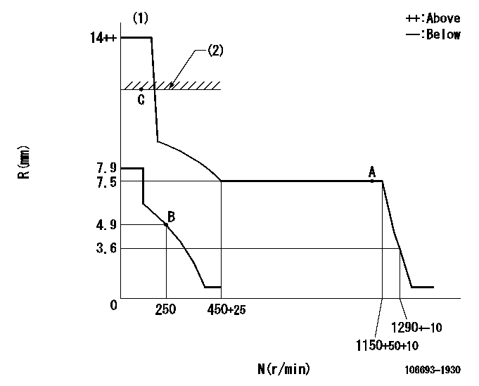
N:Pump speed
R:Rack position (mm)
(1)Target notch: K
(2)RACK LIMIT
----------
K=10
----------
----------
K=10
----------
Speed control lever angle
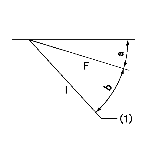
F:Full speed
I:Idle
(1)Stopper bolt setting
----------
----------
a=(4deg)+-5deg b=(24deg)+-5deg
----------
----------
a=(4deg)+-5deg b=(24deg)+-5deg
Stop lever angle

N:Pump normal
S:Stop the pump.
----------
----------
a=19deg+-5deg b=53deg+-5deg
----------
----------
a=19deg+-5deg b=53deg+-5deg
Timing setting

(1)Pump vertical direction
(2)Position of timer's threaded hole at No 1 cylinder's beginning of injection
(3)B.T.D.C.: aa
(4)-
----------
aa=14deg
----------
a=(50deg)
----------
aa=14deg
----------
a=(50deg)
Information:
Service Standards
Tightening Torque List
Tightening Torques For Main Fasteners
"Wet" means that the threads of the relevant item should be coated with engine oil before tightening.The items whose torque specifications are marked with asterisks (*) must be tightened using special tools in order that the torque may be controlled precisely.Tightening Torques for Standard Bolts and Nuts
a. The table above applies only to standardized bolts and nuts.b. All torques shown assume use of spring washer together with bolts and nuts.c. All bolts and nuts appearing in this manual should be tightened according to this table unless otherwise indicated.d. Standard bolts and nuts should be tightened in "dry" condition, without lubricating their threads with oil.Tightening Torques for Standard Eye Bolts (for Dry Condition)
Tightening Torques for Standard Union Nuts (for Dry Condition)
Tightening Torques for Taper Screws
Sealant
Have questions with 106693-1930?
Group cross 106693-1930 ZEXEL
Isuzu
106693-1930
9 400 617 917
INJECTION-PUMP ASSEMBLY
6SD1-M
6SD1-M
Isuzu
106693-1930
9 400 617 917
1156024330
INJECTION-PUMP ASSEMBLY
6SD1-M
6SD1-M