Information injection-pump assembly
ZEXEL
106693-1912
1066931912
ISUZU
1156024922
1156024922
Rating:
Service parts 106693-1912 INJECTION-PUMP ASSEMBLY:
1.
_
7.
COUPLING PLATE
8.
_
9.
_
11.
Nozzle and Holder
1-15300-218-1
12.
Open Pre:MPa(Kqf/cm2)
17.7{180}/22.1{225}
15.
NOZZLE SET
Include in #1:
106693-1912
as INJECTION-PUMP ASSEMBLY
Cross reference number
ZEXEL
106693-1912
1066931912
ISUZU
1156024922
1156024922
Zexel num
Bosch num
Firm num
Name
Calibration Data:
Adjustment conditions
Test oil
1404 Test oil ISO4113 or {SAEJ967d}
1404 Test oil ISO4113 or {SAEJ967d}
Test oil temperature
degC
40
40
45
Nozzle and nozzle holder
105780-8140
Bosch type code
EF8511/9A
Nozzle
105780-0000
Bosch type code
DN12SD12T
Nozzle holder
105780-2080
Bosch type code
EF8511/9
Opening pressure
MPa
17.2
Opening pressure
kgf/cm2
175
Injection pipe
Outer diameter - inner diameter - length (mm) mm 8-3-600
Outer diameter - inner diameter - length (mm) mm 8-3-600
Overflow valve
134424-1920
Overflow valve opening pressure
kPa
127
107
147
Overflow valve opening pressure
kgf/cm2
1.3
1.1
1.5
Tester oil delivery pressure
kPa
157
157
157
Tester oil delivery pressure
kgf/cm2
1.6
1.6
1.6
Direction of rotation (viewed from drive side)
Left L
Left L
Injection timing adjustment
Direction of rotation (viewed from drive side)
Left L
Left L
Injection order
1-5-3-6-
2-4
Pre-stroke
mm
3.7
3.67
3.73
Beginning of injection position
Governor side NO.1
Governor side NO.1
Difference between angles 1
Cal 1-5 deg. 60 59.75 60.25
Cal 1-5 deg. 60 59.75 60.25
Difference between angles 2
Cal 1-3 deg. 120 119.75 120.25
Cal 1-3 deg. 120 119.75 120.25
Difference between angles 3
Cal 1-6 deg. 180 179.75 180.25
Cal 1-6 deg. 180 179.75 180.25
Difference between angles 4
Cyl.1-2 deg. 240 239.75 240.25
Cyl.1-2 deg. 240 239.75 240.25
Difference between angles 5
Cal 1-4 deg. 300 299.75 300.25
Cal 1-4 deg. 300 299.75 300.25
Injection quantity adjustment
Adjusting point
A
Rack position
11.2
Pump speed
r/min
700
700
700
Average injection quantity
mm3/st.
162.2
160.2
164.2
Max. variation between cylinders
%
0
-3
3
Basic
*
Fixing the lever
*
Boost pressure
kPa
41.3
41.3
Boost pressure
mmHg
310
310
Injection quantity adjustment_02
Adjusting point
E
Rack position
5.5+-0.5
Pump speed
r/min
240
240
240
Average injection quantity
mm3/st.
11.6
8.4
14.8
Max. variation between cylinders
%
0
-13
13
Fixing the rack
*
Boost pressure
kPa
0
0
0
Boost pressure
mmHg
0
0
0
Boost compensator adjustment
Pump speed
r/min
500
500
500
Rack position
8.2
Boost pressure
kPa
10
8.7
11.3
Boost pressure
mmHg
75
65
85
Boost compensator adjustment_02
Pump speed
r/min
500
500
500
Rack position
9.3
Boost pressure
kPa
14
11.3
16.7
Boost pressure
mmHg
105
85
125
Boost compensator adjustment_03
Pump speed
r/min
500
500
500
Rack position
11.2
Boost pressure
kPa
28
28
28
Boost pressure
mmHg
210
210
210
Test data Ex:
Governor adjustment
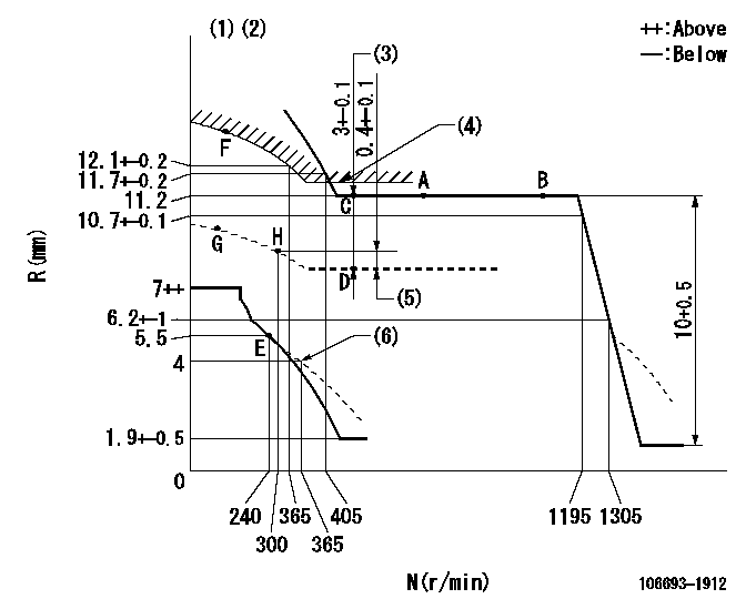
N:Pump speed
R:Rack position (mm)
(1)Supplied with torque spring not set.
(2)Tolerance for racks not indicated: +-0.05mm.
(3)Boost compensator stroke
(4)Excess fuel setting for starting: SXL (N = N1)
(5)Rack difference to N = N2
(6)Damper spring setting
----------
SXL=11.6+-0.1mm N1=400r/min N2=500r/min
----------
----------
SXL=11.6+-0.1mm N1=400r/min N2=500r/min
----------
Timer adjustment

(1)Adjusting range
(2)Step response time
(N): Speed of the pump
(L): Load
(theta) Advance angle
(Srd1) Step response time 1
(Srd2) Step response time 2
1. Adjusting conditions for the variable timer
(1)Adjust the clearance between the pickup and the protrusion to L.
----------
L=1-0.2mm N2=800r/min C2=(5.5deg) t1=2--sec. t2=2--sec.
----------
N1=800++r/min P1=0kPa(0kgf/cm2) P2=392kPa(4kgf/cm2) C1=5.5+-0.3deg R01=0/4load R02=4/4load
----------
L=1-0.2mm N2=800r/min C2=(5.5deg) t1=2--sec. t2=2--sec.
----------
N1=800++r/min P1=0kPa(0kgf/cm2) P2=392kPa(4kgf/cm2) C1=5.5+-0.3deg R01=0/4load R02=4/4load
Speed control lever angle

F:Full speed
----------
----------
a=6deg+-5deg
----------
----------
a=6deg+-5deg
0000000901
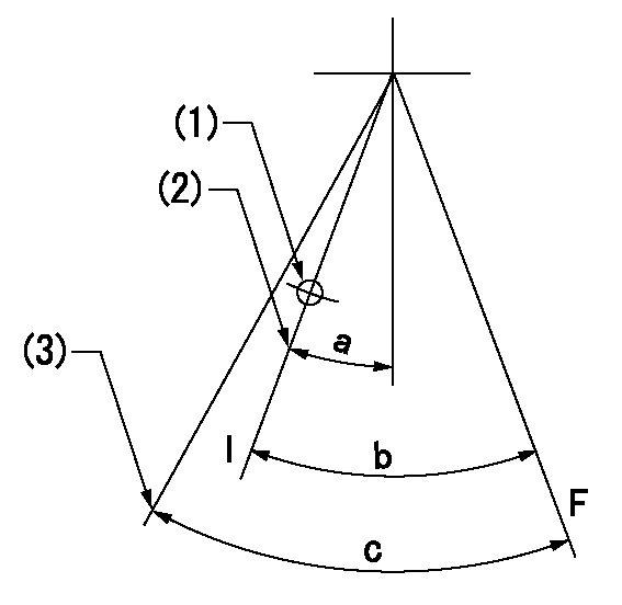
F:Full load
I:Idle
(1)Use the hole at R = aa
(2)Stopper bolt setting
(3)Accelerator lever angle after setting the accelerator lever stopper bolt
----------
aa=35mm
----------
a=15deg+-5deg b=34.5deg+-3deg c=38.5deg+-5deg
----------
aa=35mm
----------
a=15deg+-5deg b=34.5deg+-3deg c=38.5deg+-5deg
Stop lever angle

N:Pump normal
S:Stop the pump.
----------
----------
a=(37deg)+-5deg b=73deg+-5deg
----------
----------
a=(37deg)+-5deg b=73deg+-5deg
0000001501 RACK SENSOR

V1:Supply voltage
V2f:Full side output voltage
V2i:Idle side output voltage
(A) Black
(B) Yellow
(C) Red
(D) Trimmer
(E): Shaft
(F) Nut
(G) Load lever
1. Load sensor adjustment
(1)Connect as shown in the above diagram and apply supply voltage V1.
(2)Hold the load lever (G) against the full side.
(3)Turn the shaft so that the voltage between (A) and (B) is V2.
(4)Hold the load lever (G) against the idle side.
(5)Adjust (D) so that the voltage between (A) and (B) is V2i.
(6)Repeat the above adjustments.
(7)Tighten the nut (F) at the point satisfying the standards.
(8)Hold the load lever against the full side stopper and the idle side stopper.
(9)At this time, confirm that the full side output voltage is V2f and the idle side output voltage is V2i.
----------
V1=5+-0.02V V2f=0.15+0.03V V2i=2.35-0.03V
----------
----------
V1=5+-0.02V V2f=0.15+0.03V V2i=2.35-0.03V
----------
0000001601 LEVER
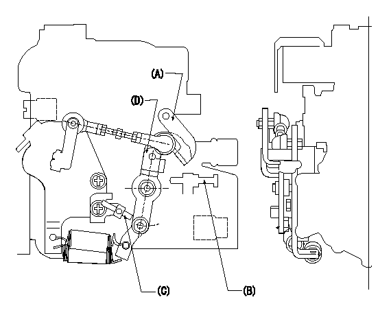
(A) Load lever (for cruise control)
(B) idle stopper bolt
(C) accelerator lever stopper bolt
(D) Accelerator lever
1. Accelerator lever stopper bolt adjustment
(1)Hold the load lever A against the idle stopper bolt and fix.
(2)Push in the accelerator lever stopper bolt C to contact the accelerator lever D.
(3)From this position, back off the idle stopper bolt B N turns (L) and set.
----------
N=1~1.5 L=0.8~1.2mm
----------
----------
N=1~1.5 L=0.8~1.2mm
----------
Timing setting

(1)Pump vertical direction
(2)Position of timer's threaded hole at No 1 cylinder's beginning of injection
(3)B.T.D.C.: aa
(4)-
----------
aa=10deg
----------
a=(40deg)
----------
aa=10deg
----------
a=(40deg)
Information:
Disassembling alternator(2) Removing Pulley(a) Wrap cloth around the rotor, then clamp the rotor in a vise. Remove the pulley nut and then the pulley and spacer.(b) Pull the rotor out of the front bracket.
Removing pulley(3) Removing Stator and Rectifier(a) Unsolder from the rectifier the leads that connect the rectifier to the stator coils. Then, remove the stator.
Unsolder the leads quickly to prevent heat from damaging the diodes.
(b) Remove the rectifier's mounting screws, then remove the rectifier.
Removing stator3.4 Inspection KEY POINTS FOR INSPECTION(1) Inspecting RectifierWith each diode, measure the resistance between the diode terminal and the heat sink. Measure the resistance with the tester's (+) probe applied to the diode terminal and with the tester's (-) probe applied to the diode terminal. If the resistance is infinite in both cases, there is an open circuit. If the resistance is close to zero in both cases, there is a short circuit. An open circuit or short circuit indicates a diode fault. Replace the rectifier if any diode is faulty.Next, measure the resistance between the terminals of the leads that connect the rectifier to the stator coil for each of the diodes. If any measurement reveals an open circuit (infinite resistance) or a short circuit (near-zero resistance), replace the rectifier.
Inspecting rectifier(2) Inspecting Field Coil(a) Check whether continuity exists between the rotor's slip rings. If continuity does not exist, the field coil is open-circuited and the rotor must be replaced.
Field coil continuity test(b) Check whether continuity exists between each slip ring and the rotor shaft (or core). If continuity exists, the field coil is grounded and the rotor must be replaced.
Field coil ground test(3) Inspecting Stator Coils(a) Check whether continuity exists between the leads at the ends of each stator coil. If continuity does not exist between any coil's leads, there is an open circuit and the stator must be replaced.
Stator coil continuity test(b) Check whether continuity exists between each stator coil lead and the stator core. If continuity exists, the stator coil is grounded and the stator must be replaced.
Stator coil ground test(4) Inspecting Brushes(a) Replace the brush if it is worn down to the wear limit line.
Inspecting brush(b) To replace the brush, remove the cover (see the drawing) then unsolder and take out the brush set.
Replacing brush3.5 AssemblyPerform assembly by following the disassembly sequence in reverse. KEY POINTS FOR ASSEMBLY(1) Heat the rear bracket before press-fitting the rear bearing into it. Do not apply oil or grease to the outer or inner surface of the bearing.(2) Before fitting the rotor in the rear bracket, insert a thin metal rod into the small hole in the rear bracket to keep the brushes raised. Remove the metal rod when assembly is complete.
Assembling alternator3.6 InstallationPerform installation by following the removal sequence in reverse. KEY POINTS FOR INSTALLATION Insertion of spacer and clearance adjustmentInstallation of the support bolt is accompanied by insertion of a spacer. Install the spacer as follows:(a) Insert the support bolt into pinion. (Do not install the nut.)(b) Install the alternator