Information injection-pump assembly
ZEXEL
106693-1902
1066931902
ISUZU
1156024912
1156024912
Rating:
Cross reference number
ZEXEL
106693-1902
1066931902
ISUZU
1156024912
1156024912
Zexel num
Bosch num
Firm num
Name
Calibration Data:
Adjustment conditions
Test oil
1404 Test oil ISO4113 or {SAEJ967d}
1404 Test oil ISO4113 or {SAEJ967d}
Test oil temperature
degC
40
40
45
Nozzle and nozzle holder
105780-8140
Bosch type code
EF8511/9A
Nozzle
105780-0000
Bosch type code
DN12SD12T
Nozzle holder
105780-2080
Bosch type code
EF8511/9
Opening pressure
MPa
17.2
Opening pressure
kgf/cm2
175
Injection pipe
Outer diameter - inner diameter - length (mm) mm 8-3-600
Outer diameter - inner diameter - length (mm) mm 8-3-600
Overflow valve
134424-1920
Overflow valve opening pressure
kPa
127
107
147
Overflow valve opening pressure
kgf/cm2
1.3
1.1
1.5
Tester oil delivery pressure
kPa
157
157
157
Tester oil delivery pressure
kgf/cm2
1.6
1.6
1.6
Direction of rotation (viewed from drive side)
Left L
Left L
Injection timing adjustment
Direction of rotation (viewed from drive side)
Left L
Left L
Injection order
1-5-3-6-
2-4
Pre-stroke
mm
3.7
3.67
3.73
Beginning of injection position
Governor side NO.1
Governor side NO.1
Difference between angles 1
Cal 1-5 deg. 60 59.75 60.25
Cal 1-5 deg. 60 59.75 60.25
Difference between angles 2
Cal 1-3 deg. 120 119.75 120.25
Cal 1-3 deg. 120 119.75 120.25
Difference between angles 3
Cal 1-6 deg. 180 179.75 180.25
Cal 1-6 deg. 180 179.75 180.25
Difference between angles 4
Cyl.1-2 deg. 240 239.75 240.25
Cyl.1-2 deg. 240 239.75 240.25
Difference between angles 5
Cal 1-4 deg. 300 299.75 300.25
Cal 1-4 deg. 300 299.75 300.25
Injection quantity adjustment
Adjusting point
A
Rack position
9
Pump speed
r/min
600
600
600
Average injection quantity
mm3/st.
160.4
158.4
162.4
Max. variation between cylinders
%
0
-3
3
Basic
*
Fixing the lever
*
Boost pressure
kPa
48
48
Boost pressure
mmHg
360
360
Injection quantity adjustment_02
Adjusting point
B
Rack position
8.9
Pump speed
r/min
1100
1100
1100
Average injection quantity
mm3/st.
162.3
160.3
164.3
Fixing the lever
*
Boost pressure
kPa
48
48
Boost pressure
mmHg
360
360
Injection quantity adjustment_03
Adjusting point
D
Rack position
4.9+-0.5
Pump speed
r/min
235
235
235
Average injection quantity
mm3/st.
12.5
9.3
15.7
Max. variation between cylinders
%
0
-13
13
Fixing the rack
*
Boost pressure
kPa
0
0
0
Boost pressure
mmHg
0
0
0
Boost compensator adjustment
Pump speed
r/min
600
600
600
Rack position
6.9
Boost pressure
kPa
10
8.7
11.3
Boost pressure
mmHg
75
65
85
Boost compensator adjustment_02
Pump speed
r/min
600
600
600
Rack position
7.9
Boost pressure
kPa
17.3
14.6
20
Boost pressure
mmHg
130
110
150
Boost compensator adjustment_03
Pump speed
r/min
600
600
600
Rack position
8.5
Boost pressure
kPa
23.3
20
26.6
Boost pressure
mmHg
175
150
200
Boost compensator adjustment_04
Pump speed
r/min
600
600
600
Rack position
9
Boost pressure
kPa
34.7
34.7
34.7
Boost pressure
mmHg
260
260
260
Test data Ex:
Governor adjustment
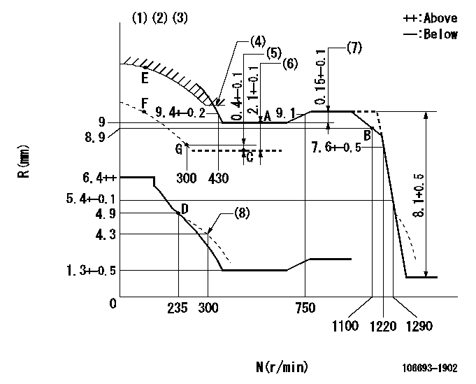
N:Pump speed
R:Rack position (mm)
(1)Lever ratio: RT
(2)Target shim dimension: TH
(3)Tolerance for racks not indicated: +-0.05mm.
(4)Excess fuel setting for starting: SXL
(5)Rack difference from N = N1
(6)Boost compensator stroke
(7)Rack difference between N = N2 and N = N3
(8)Damper spring setting
----------
RT=0.8 TH=2.8mm SXL=9.6+-0.1mm N1=500r/min N2=900r/min N3=600r/min
----------
----------
RT=0.8 TH=2.8mm SXL=9.6+-0.1mm N1=500r/min N2=900r/min N3=600r/min
----------
Timer adjustment

(1)Adjusting range
(2)Step response time
(N): Speed of the pump
(L): Load
(theta) Advance angle
(Srd1) Step response time 1
(Srd2) Step response time 2
1. Adjusting conditions for the variable timer
(1)Adjust the clearance between the pickup and the protrusion to L.
----------
L=1-0.2mm N2=800r/min C2=(5.5)deg t1=2--sec. t2=2--sec.
----------
N1=800++r/min P1=0kPa(0kgf/cm2) P2=392kPa(4kgf/cm2) C1=5.5+-0.3deg R01=0/4load R02=4/4load
----------
L=1-0.2mm N2=800r/min C2=(5.5)deg t1=2--sec. t2=2--sec.
----------
N1=800++r/min P1=0kPa(0kgf/cm2) P2=392kPa(4kgf/cm2) C1=5.5+-0.3deg R01=0/4load R02=4/4load
Speed control lever angle

F:Full speed
----------
----------
a=5deg+-5deg
----------
----------
a=5deg+-5deg
0000000901

F:Full load
I:Idle
(1)Stopper bolt setting
(2)Use the hole at R = aa
----------
aa=35mm
----------
a=15deg+-5deg b=41deg+-3deg
----------
aa=35mm
----------
a=15deg+-5deg b=41deg+-3deg
Stop lever angle

N:Pump normal
S:Stop the pump.
----------
----------
a=37deg+-5deg b=73deg+-5deg
----------
----------
a=37deg+-5deg b=73deg+-5deg
0000001501 RACK SENSOR

V1:Supply voltage
V2f:Full side output voltage
V2i:Idle side output voltage
(A) Black
(B) Yellow
(C) Red
(D) Trimmer
(E): Shaft
(F) Nut
(G) Load lever
1. Load sensor adjustment
(1)Connect as shown in the above diagram and apply supply voltage V1.
(2)Hold the load lever (G) against the full side.
(3)Turn the shaft so that the voltage between (A) and (B) is V2.
(4)Hold the load lever (G) against the idle side.
(5)Adjust (D) so that the voltage between (A) and (B) is V2i.
(6)Repeat the above adjustments.
(7)Tighten the nut (F) at the point satisfying the standards.
(8)Hold the load lever against the full side stopper and the idle side stopper.
(9)At this time, confirm that the full side output voltage is V2f and the idle side output voltage is V2i.
----------
V1=5+-0.02V V2f=0.15+0.03V V2i=2.35-0.03V
----------
----------
V1=5+-0.02V V2f=0.15+0.03V V2i=2.35-0.03V
----------
Timing setting

(1)Pump vertical direction
(2)Position of timer's threaded hole at No 1 cylinder's beginning of injection
(3)B.T.D.C.: aa
(4)-
----------
aa=10deg
----------
a=(40deg)
----------
aa=10deg
----------
a=(40deg)
Information:
5.3 Assembly
Assembly sequence: piston and connecting rod assemblies and crankshaftThe assembly sequence is indicated by the numbers in the drawing above. KEY POINTS FOR ASSEMBLY(1) Installing Main Bearings(a) Press the main bearings (upper and lower) into the cylinder block and main bearing caps, respectively, such that the bearings' lugs fit into the grooves.
Installing main bearings(b) Fit the flanged main bearing in the No. 3 journal position.(c) Smear a little engine oil on the inner surface of each bearing.
Installing flanged main bearing(2) Installing Crankshaft(a) Wash the crankshaft thoroughly in cleaning solvent, then dry it with compressed air.(b) Keeping the crankshaft horizontal, gently lower it into the cylinder block.(c) Smear a little engine oil on each crankshaft journal.
Installing crankshaft(3) Installing Main Bearing Caps(a) Before installing the main bearing caps, apply sealant to the mating surfaces of the frontmost and rearmost caps and to the corresponding surfaces in the cylinder block.
Installing main bearing caps(b) Referring to the cap numbers, fit the main bearing caps sequentially starting at the front of the engine. The arrow on each cap must point toward the front of the engine.
Make sure the frontmost and rearmost caps fit flush against the cylinder block.
Front marks and cap numbers(4) Tightening Bearing Cap BoltsTighten the bearing cap bolts alternately a little at a time, then torque each bolt to specification.
Tightening bearing cap bolts(5) Checking Crankshaft RotationConfirm that the crankshaft turns smoothly.
Checking crankshaft rotation(6) Measuring End Play of CrankshaftApply a dial gauge to the end of the crankshaft and measure the end play. If the measurement exceeds the specified limit, replace the No. 3 flanged bearing.
Unit: mm (in.)
Measuring end play of crankshaft(7) Inserting Side Seals(a) Apply sealant to the mating surfaces of each side seal. (b) With the radius of each side seal facing the outside, push the side seals part-way into the frontmost and rearmost caps by hand.
Alignment of side seals for installation(c) Press each side seal completely into position using a flat implement. Be careful not to bend the side seals.
Inserting side seals(8) Preparation for Installation of Piston and Connecting Rod Assemblies(a) Clean each cylinder's inner surface with a rag, then smear each with engine oil.(b) Press the connecting rod bearings (upper and lower) into the connecting rods and caps such that the bearings' lugs fit into the grooves.(c) Smear the connecting rod bearings with engine oil.(d) Turn the cylinder block onto its side.
Preparation for installation of piston and connecting rod assemblies(9) Preparation for Installation of Piston and Connecting Rod Assemblies(a) Smear the pistons' sliding surfaces and piston rings with engine oil.(b) Position the piston ring gaps as shown in the drawing. Do not align any ring gap with the piston pin or at 90° to the piston pin.
Piston ring positions(c) Turn the crankshaft until the crank pin onto which the connecting rod is to be fitted reaches its TDC position.(d) Align the piston such that its front mark (this is stamped on the piston crown) points toward the timing gear case mounting surface (the front of the engine).(e)