Information injection-pump assembly
ZEXEL
106693-1893
1066931893
ISUZU
1156024673
1156024673
Rating:
Cross reference number
ZEXEL
106693-1893
1066931893
ISUZU
1156024673
1156024673
Zexel num
Bosch num
Firm num
Name
Calibration Data:
Adjustment conditions
Test oil
1404 Test oil ISO4113 or {SAEJ967d}
1404 Test oil ISO4113 or {SAEJ967d}
Test oil temperature
degC
40
40
45
Nozzle and nozzle holder
105780-8140
Bosch type code
EF8511/9A
Nozzle
105780-0000
Bosch type code
DN12SD12T
Nozzle holder
105780-2080
Bosch type code
EF8511/9
Opening pressure
MPa
17.2
Opening pressure
kgf/cm2
175
Injection pipe
Outer diameter - inner diameter - length (mm) mm 8-3-600
Outer diameter - inner diameter - length (mm) mm 8-3-600
Overflow valve
134424-1920
Overflow valve opening pressure
kPa
127
107
147
Overflow valve opening pressure
kgf/cm2
1.3
1.1
1.5
Tester oil delivery pressure
kPa
157
157
157
Tester oil delivery pressure
kgf/cm2
1.6
1.6
1.6
Direction of rotation (viewed from drive side)
Left L
Left L
Injection timing adjustment
Direction of rotation (viewed from drive side)
Left L
Left L
Injection order
1-5-3-6-
2-4
Pre-stroke
mm
3.7
3.67
3.73
Beginning of injection position
Governor side NO.1
Governor side NO.1
Difference between angles 1
Cal 1-5 deg. 60 59.75 60.25
Cal 1-5 deg. 60 59.75 60.25
Difference between angles 2
Cal 1-3 deg. 120 119.75 120.25
Cal 1-3 deg. 120 119.75 120.25
Difference between angles 3
Cal 1-6 deg. 180 179.75 180.25
Cal 1-6 deg. 180 179.75 180.25
Difference between angles 4
Cyl.1-2 deg. 240 239.75 240.25
Cyl.1-2 deg. 240 239.75 240.25
Difference between angles 5
Cal 1-4 deg. 300 299.75 300.25
Cal 1-4 deg. 300 299.75 300.25
Injection quantity adjustment
Adjusting point
A
Rack position
9
Pump speed
r/min
600
600
600
Average injection quantity
mm3/st.
160.4
158.4
162.4
Max. variation between cylinders
%
0
-3
3
Basic
*
Fixing the lever
*
Boost pressure
kPa
48
48
Boost pressure
mmHg
360
360
Injection quantity adjustment_02
Adjusting point
B
Rack position
8.9
Pump speed
r/min
1100
1100
1100
Average injection quantity
mm3/st.
162.3
160.3
164.3
Fixing the lever
*
Boost pressure
kPa
48
48
Boost pressure
mmHg
360
360
Injection quantity adjustment_03
Adjusting point
D
Rack position
4.9+-0.5
Pump speed
r/min
235
235
235
Average injection quantity
mm3/st.
12.5
9.3
15.7
Max. variation between cylinders
%
0
-13
13
Fixing the rack
*
Boost pressure
kPa
0
0
0
Boost pressure
mmHg
0
0
0
Boost compensator adjustment
Pump speed
r/min
600
600
600
Rack position
6.9
Boost pressure
kPa
10
8.7
11.3
Boost pressure
mmHg
75
65
85
Boost compensator adjustment_02
Pump speed
r/min
600
600
600
Rack position
7.9
Boost pressure
kPa
17.3
14.6
20
Boost pressure
mmHg
130
110
150
Boost compensator adjustment_03
Pump speed
r/min
600
600
600
Rack position
8.5
Boost pressure
kPa
23.3
20
26.6
Boost pressure
mmHg
175
150
200
Boost compensator adjustment_04
Pump speed
r/min
600
600
600
Rack position
9
Boost pressure
kPa
34.7
34.7
34.7
Boost pressure
mmHg
260
260
260
Test data Ex:
Governor adjustment
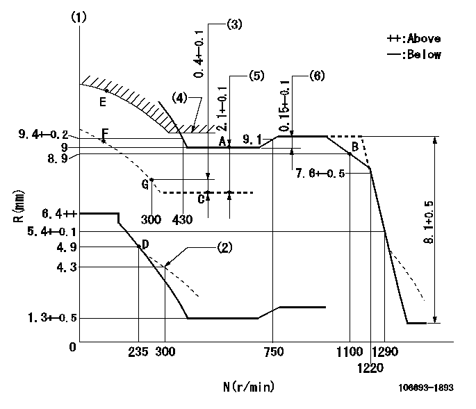
N:Pump speed
R:Rack position (mm)
(1)Tolerance for racks not indicated: +-0.05mm.
(2)Damper spring setting
(3)Rack difference from N = N1
(4)Boost compensator stroke
(5)Excess fuel setting for starting: SXL
(6)Rack difference between N = N2 and N = N3
----------
N1=500r/min SXL=9.6+-0.1mm N2=900r/min N3=600r/min
----------
----------
N1=500r/min SXL=9.6+-0.1mm N2=900r/min N3=600r/min
----------
Timer adjustment

(1)Adjusting range
(2)Step response time
(N): Speed of the pump
(L): Load
(theta) Advance angle
(Srd1) Step response time 1
(Srd2) Step response time 2
1. Adjusting conditions for the variable timer
(1)Adjust the clearance between the pickup and the protrusion to L.
----------
L=1-0.2mm N2=800r/min C2=(5.5)deg t1=2--sec. t2=2--sec.
----------
N1=800++r/min P1=0kPa(0kgf/cm2) P2=392kPa(4kgf/cm2) C1=5.5+-0.3deg R01=0/4load R02=4/4load
----------
L=1-0.2mm N2=800r/min C2=(5.5)deg t1=2--sec. t2=2--sec.
----------
N1=800++r/min P1=0kPa(0kgf/cm2) P2=392kPa(4kgf/cm2) C1=5.5+-0.3deg R01=0/4load R02=4/4load
Speed control lever angle

F:Full speed
----------
----------
a=5deg+-5deg
----------
----------
a=5deg+-5deg
0000000901
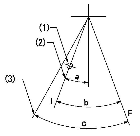
F:Full load
I:Idle
(1)Use the hole at R = aa
(2)Stopper bolt setting
(3)Accelerator lever angle after setting the accelerator lever stopper bolt
----------
aa=35mm
----------
a=15deg+-5deg b=41deg+-3deg c=45.5deg+-5deg
----------
aa=35mm
----------
a=15deg+-5deg b=41deg+-3deg c=45.5deg+-5deg
Stop lever angle

N:Pump normal
S:Stop the pump.
----------
----------
a=37deg+-5deg b=73deg+-5deg
----------
----------
a=37deg+-5deg b=73deg+-5deg
0000001501 RACK SENSOR

V1:Supply voltage
V2f:Full side output voltage
V2i:Idle side output voltage
(A) Black
(B) Yellow
(C) Red
(D) Trimmer
(E): Shaft
(F) Nut
(G) Load lever
1. Load sensor adjustment
(1)Connect as shown in the above diagram and apply supply voltage V1.
(2)Hold the load lever (G) against the full side.
(3)Turn the shaft so that the voltage between (A) and (B) is V2.
(4)Hold the load lever (G) against the idle side.
(5)Adjust (D) so that the voltage between (A) and (B) is V2i.
(6)Repeat the above adjustments.
(7)Tighten the nut (F) at the point satisfying the standards.
(8)Hold the load lever against the full side stopper and the idle side stopper.
(9)At this time, confirm that the full side output voltage is V2f and the idle side output voltage is V2i.
----------
V1=5+-0.02V V2f=0.15+0.03V V2i=2.35-0.03V
----------
----------
V1=5+-0.02V V2f=0.15+0.03V V2i=2.35-0.03V
----------
0000001601 LEVER
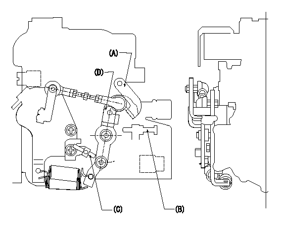
(A) Load lever (for cruise control)
(B) idle stopper bolt
(C) accelerator lever stopper bolt
(D) Accelerator lever
1. Accelerator lever stopper bolt adjustment
(1)Hold the load lever A against the idle stopper bolt and fix.
(2)Push in the accelerator lever stopper bolt C to contact the accelerator lever D.
(3)From this position, back off the idle stopper bolt B N turns (L) and set.
----------
N=1~1.5 L=0.8~1.2mm
----------
----------
N=1~1.5 L=0.8~1.2mm
----------
Timing setting

(1)Pump vertical direction
(2)Position of timer's threaded hole at No 1 cylinder's beginning of injection
(3)B.T.D.C.: aa
(4)-
----------
aa=10deg
----------
a=(45deg)
----------
aa=10deg
----------
a=(45deg)
Information:
1. Overview
1.1 External Views 1.2 Engine Model and Engine Serial Number(1) The engine model code is embossed next to the injection pump on the right-hand side of the cylinder block.
Engine model and total displacement(2) The engine serial number is shown by a label attached to the top of the rocker cover. It is also stamped on the injection pump mounting surface of the cylinder block.(3) The engine serial number is stamped as shown below:
Location of engine serial number label1.3 Engine Model and Application Codes(1) The engine model code is designated as shown below.* Engine model and classification * Model code 2. Specifications
2.1 Major Specifications 3. Points to Note for Disassembly and Reassembly
This service manual contains recommended service procedures for your Mitsubishi diesel engine. It also contains information on special tools and basic safety precautions. Since hazards exist in many places, the safety precautions in this manual should not be considered exhaustive. It is your responsibility to exercise common sense and to pay attention to safety at all times.Always perform service operations in accordance with this manual. When performing disassembly and reassembly operations, also observe the general instructions given below.3.1 Disassembly(1) Use only the correct tools and instruments.(2) Use an overhaul stand or work bench if necessary, and make ready a surface where removed parts can be arranged. Remove parts in the specified disassembly sequence.(3) Arrange disassembled parts neatly to avoid losing them.(4) Pay attention to alignment and position marks. If necessary, make your own marks to facilitate reassembly.(5) Carefully check parts for abnormalities when removing or cleaning them. Abnormalities may be harder to see after parts have been removed or cleaned.(6) Strive to ensure safety at all times. It is particularly important to make sure that items being disassembled are properly balanced and to pay attention to safety when moving heavy items. Use jacks and chain blocks when necessary.3.2 Reassembly(1) Wash all engine parts (except oil seals, O-rings, and rubber seals) in cleaning solvent and dry them with compressed air.(2) Use only the correct tools and instruments.(3) Use only high-quality oils and greases of the specified types. Be sure to apply a coat of oil, grease, or sealant wherever specified.(4) Use a torque wrench to achieve all specified tightening torques.(5) As a general rule, all gaskets and seals must be replaced with new ones. Apply adhesive where required, and be careful not to apply too much.