Information injection-pump assembly
ZEXEL
106693-1392
1066931392
ISUZU
1156016672
1156016672
Rating:
Service parts 106693-1392 INJECTION-PUMP ASSEMBLY:
1.
_
7.
COUPLING PLATE
8.
_
9.
_
11.
Nozzle and Holder
1-15300-128-2
12.
Open Pre:MPa(Kqf/cm2)
17.7{180}
15.
NOZZLE SET
Include in #1:
106693-1392
as INJECTION-PUMP ASSEMBLY
Cross reference number
ZEXEL
106693-1392
1066931392
ISUZU
1156016672
1156016672
Zexel num
Bosch num
Firm num
Name
Calibration Data:
Adjustment conditions
Test oil
1404 Test oil ISO4113 or {SAEJ967d}
1404 Test oil ISO4113 or {SAEJ967d}
Test oil temperature
degC
40
40
45
Nozzle and nozzle holder
105780-8140
Bosch type code
EF8511/9A
Nozzle
105780-0000
Bosch type code
DN12SD12T
Nozzle holder
105780-2080
Bosch type code
DN12SD12T
Opening pressure
MPa
17.2
Opening pressure
kgf/cm2
175
Injection pipe
Outer diameter - inner diameter - length (mm) mm 8-3-600
Outer diameter - inner diameter - length (mm) mm 8-3-600
Overflow valve
134424-1920
Overflow valve opening pressure
kPa
127
107
147
Overflow valve opening pressure
kgf/cm2
1.3
1.1
1.5
Tester oil delivery pressure
kPa
157
157
157
Tester oil delivery pressure
kgf/cm2
1.6
1.6
1.6
Direction of rotation (viewed from drive side)
Right R
Right R
Injection timing adjustment
Direction of rotation (viewed from drive side)
Right R
Right R
Injection order
1-4-2-6-
3-5
Pre-stroke
mm
3
2.97
3.03
Beginning of injection position
Drive side NO.1
Drive side NO.1
Difference between angles 1
Cal 1-4 deg. 60 59.75 60.25
Cal 1-4 deg. 60 59.75 60.25
Difference between angles 2
Cyl.1-2 deg. 120 119.75 120.25
Cyl.1-2 deg. 120 119.75 120.25
Difference between angles 3
Cal 1-6 deg. 180 179.75 180.25
Cal 1-6 deg. 180 179.75 180.25
Difference between angles 4
Cal 1-3 deg. 240 239.75 240.25
Cal 1-3 deg. 240 239.75 240.25
Difference between angles 5
Cal 1-5 deg. 300 299.75 300.25
Cal 1-5 deg. 300 299.75 300.25
Injection quantity adjustment
Adjusting point
A
Rack position
6.8
Pump speed
r/min
1150
1150
1150
Average injection quantity
mm3/st.
118
116
120
Max. variation between cylinders
%
0
-4
4
Fixing the lever
*
Injection quantity adjustment_02
Adjusting point
B
Rack position
6.4
Pump speed
r/min
700
700
700
Average injection quantity
mm3/st.
97.7
95.7
99.7
Max. variation between cylinders
%
0
-3
3
Basic
*
Fixing the lever
*
Injection quantity adjustment_03
Adjusting point
-
Rack position
4.2+-0.5
Pump speed
r/min
225
225
225
Average injection quantity
mm3/st.
13
9.8
16.2
Max. variation between cylinders
%
0
-13
13
Fixing the rack
*
Remarks
Adjust only variation between cylinders; adjust governor according to governor specifications.
Adjust only variation between cylinders; adjust governor according to governor specifications.
Injection quantity adjustment_04
Adjusting point
E
Rack position
7.7+-0.5
Pump speed
r/min
300
300
300
Average injection quantity
mm3/st.
109.6
106.6
112.6
Fixing the lever
*
Remarks
Startup boost setting
Startup boost setting
Injection quantity adjustment_05
Adjusting point
F
Rack position
7.2+-0.5
Pump speed
r/min
350
350
350
Average injection quantity
mm3/st.
101.4
98.4
104.4
Fixing the lever
*
Timer adjustment
Pump speed
r/min
900+50
Advance angle
deg.
0
0
0
Remarks
Start
Start
Timer adjustment_02
Pump speed
r/min
1150
Advance angle
deg.
5.5
5
6
Remarks
Finish
Finish
Test data Ex:
Governor adjustment
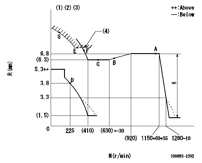
N:Pump speed
R:Rack position (mm)
(1)Lever ratio: RT
(2)Target shim dimension: TH
(3)Damper spring setting: DL
(4)Excess fuel setting for starting: SXL
----------
RT=0.8 TH=2.4mm DL=3.3-0.5mm SXL=(7.7)+-0.1mm
----------
----------
RT=0.8 TH=2.4mm DL=3.3-0.5mm SXL=(7.7)+-0.1mm
----------
Speed control lever angle

F:Full speed
----------
----------
a=5deg+-5deg
----------
----------
a=5deg+-5deg
0000000901
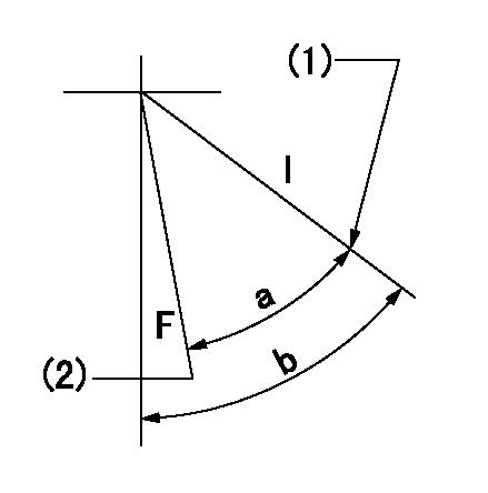
F:Full load
I:Idle
(1)Stopper bolt setting
(2)Attach the return spring to the bottom hole and adjust.
----------
----------
a=(26deg)+-3deg b=55deg+-5deg
----------
----------
a=(26deg)+-3deg b=55deg+-5deg
Stop lever angle

N:Pump normal
S:Stop the pump.
----------
----------
a=52deg+-5deg b=64deg+-5deg
----------
----------
a=52deg+-5deg b=64deg+-5deg
0000001501 MICRO SWITCH
Adjustment of the micro-switch
Adjust the bolt to obtain the following lever position when the micro-switch is ON.
(1)Speed N1
(2)Rack position Ra
----------
N1=325r/min Ra=3.8mm
----------
----------
N1=325r/min Ra=3.8mm
----------
0000001601 GOVERNOR TORQUE CONTROL

Dr:Torque control stroke
(A): Without torque control spring capsule
1. Adjustment procedures
(1)Procedure is the same as that for the RFD (former type), except that the positive torque control stroke must be determined at the full lever setting.
2. Procedures for adjustment
(1)Remove the torque control spring capsule.
(2)Operate the pump at approximately N1. (End of idling spring operation < N1.)
(3)Tilt the lever to the full side.
(4)Set so that R = RF.
(5)Increase the speed by pushing in the screw (attached to the bracket on the rear of the tension lever) through the adjusting window.
(6)Adjust so that the torque control stroke Dr1 can be obtained.
(7)Align N2 and N3 with the torque control spring capsule.
3. Final confirmation
(1)After final confirmation, temporarily set the load lever to N = N1, R = idling position.
(2)From this condition, increase speed to N = N4.
(3)Confirm that positive torque control stroke is Dr2.
----------
N1=500r/min N2=(630)+-30r/min N3=(920)r/min N4=1100r/min RF=(6.3)mm Dr1=0.5mm Dr2=0+0.3mm
----------
----------
N1=500r/min N2=(630)+-30r/min N3=(920)r/min N4=1100r/min RF=(6.3)mm Dr1=0.5mm Dr2=0+0.3mm
----------
Timing setting

(1)Pump vertical direction
(2)Position of timer's threaded hole at No 1 cylinder's beginning of injection
(3)B.T.D.C.: aa
(4)-
----------
aa=14deg
----------
a=(60deg)
----------
aa=14deg
----------
a=(60deg)
Information:
Features and Benefits
Cat Reman Fuel Injectors and Nozzles offer excellent value to customers. Customers who want fast repair turn-around, superior quality and reliability, and lower repair costs will benefit from the use of these remanufactured fuel injectors and nozzles. Cat Reman Fuel Injectors and Nozzles provide immediate, off-the-shelf availability at a fraction of the new price.
Features Benefits
All critical engineering changes and updates included Improved reliability and performance
Worldwide availability through Caterpillar? parts distribution system Customer access regardless of location
Backed by Cat parts warranty Consistent support
Core Acceptance
Core Acceptance Criteria for Caterpillar Remanufactured Fuel Injectors and Nozzles is simple, visual, and requires no special tools. Please see the table below for applicable Core Acceptance Criteria for each Injector or Nozzle type.
Type Applicable Core Acceptance Criteria
Direct Injection Fuel Nozzles - Direct Injection (SELD0224)
Mechanical Unit Unit Injectors Mechanical (SELD0030-04)
Electronic Unit Unit Injectors - Electronic (SELD0226)
Warranty
Please consult the appropriate Cat?parts warranty statement for your area.
Availability
All of the above fuel injectors and nozzles are currently available for ordering. Some of these Reman Fuel Injectors and Nozzles are currently on initial seed support. For parts on initial seed support Antares may show "0" on-hand quantity for the Reman part number, however, orders for Reman will be filled with the new part equivalent. When Reman is the preferred option always order under the Reman part number regardless of what the system shows for on-hand. As long as the new equivalent part number has on-hand available the Reman order will be filled.
Core Management
Please refer to the Caterpillar Core Management Information System (CMIS 2) Parts Information application describing all Cat Reman part/CAF and related information. Also refer to other CMIS 2 inquiry applications such as Customer Profiles, Inspection Reason Codes, Inspection Line Inquiry, Add Charge Information, Entitlement Activity, Entitlement Inquiry, CCR Inquiry, CCR Entry, Shipment Processing; Process Packaging Grief; and Reporting to properly manage core returns and monitor inspection performance. This information will be available to all dealers worldwide after your CMIS 2 conversion date. In the meantime, please continue to use the current CMIS Entitlement Parts Inquiry Screen describing the list of parts in a Core Acceptability Family (CAF) and related part number detail.
For the latest updates of Reman Policies and Core Management (SELD0122), Core Management Systems & Operations Procedures (SELD0040), and Shipping Instructions (SELD0039), go to the Reman Dealer website https://catreman.cat.com
If you have any questions regarding core return processing, feel free to call Corinth toll free at (800) 537-2928. For assistance with technical questions, call the Peoria Reman Technical Help Line also toll free at (888) 88-REMAN or use our E-mail address--Reman_Help.