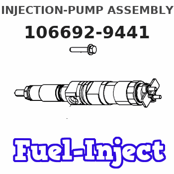
Information injection-pump assembly
ZEXEL
106692-9441
1066929441
KOMATSU
6151721810
6151721810
Rating:
Service parts 106692-9441 INJECTION-PUMP ASSEMBLY:
1.
_
2.
FUEL INJECTION PUMP
5.
AUTOM. ADVANCE MECHANIS
8.
_
9.
_
11.
Nozzle and Holder
12.
Open Pre:MPa(Kqf/cm2)
24.5(250)
15.
NOZZLE SET
Include in #1:
106692-9441
as INJECTION-PUMP ASSEMBLY
Cross reference number
ZEXEL
106692-9441
1066929441
KOMATSU
6151721810
6151721810
Zexel num
Bosch num
Firm num
Name
Calibration Data:
Adjustment conditions
Test oil
1404 Test oil ISO4113 or {SAEJ967d}
1404 Test oil ISO4113 or {SAEJ967d}
Test oil temperature
degC
40
40
45
Nozzle and nozzle holder
105780-8140
Bosch type code
EF8511/9A
Nozzle
105780-0000
Bosch type code
DN12SD12T
Nozzle holder
105780-2080
Bosch type code
EF8511/9
Opening pressure
MPa
17.2
Opening pressure
kgf/cm2
175
Injection pipe
Outer diameter - inner diameter - length (mm) mm 8-3-600
Outer diameter - inner diameter - length (mm) mm 8-3-600
Overflow valve
131424-1520
Overflow valve opening pressure
kPa
157
123
191
Overflow valve opening pressure
kgf/cm2
1.6
1.25
1.95
Tester oil delivery pressure
kPa
157
157
157
Tester oil delivery pressure
kgf/cm2
1.6
1.6
1.6
Direction of rotation (viewed from drive side)
Left L
Left L
Injection timing adjustment
Direction of rotation (viewed from drive side)
Left L
Left L
Injection order
1-5-3-6-
2-4
Pre-stroke
mm
3.75
3.7
3.8
Beginning of injection position
Drive side NO.1
Drive side NO.1
Difference between angles 1
Cal 1-5 deg. 60 59.5 60.5
Cal 1-5 deg. 60 59.5 60.5
Difference between angles 2
Cal 1-3 deg. 120 119.5 120.5
Cal 1-3 deg. 120 119.5 120.5
Difference between angles 3
Cal 1-6 deg. 180 179.5 180.5
Cal 1-6 deg. 180 179.5 180.5
Difference between angles 4
Cyl.1-2 deg. 240 239.5 240.5
Cyl.1-2 deg. 240 239.5 240.5
Difference between angles 5
Cal 1-4 deg. 300 299.5 300.5
Cal 1-4 deg. 300 299.5 300.5
Injection quantity adjustment
Adjusting point
A
Rack position
8.5
Pump speed
r/min
1050
1050
1050
Average injection quantity
mm3/st.
109
107
111
Max. variation between cylinders
%
0
-3
3
Basic
*
Fixing the lever
*
Injection quantity adjustment_02
Adjusting point
-
Rack position
6.7+-0.5
Pump speed
r/min
340
340
340
Average injection quantity
mm3/st.
17
15.5
18.5
Max. variation between cylinders
%
0
-15
15
Fixing the rack
*
Remarks
Adjust only variation between cylinders; adjust governor according to governor specifications.
Adjust only variation between cylinders; adjust governor according to governor specifications.
Test data Ex:
Governor adjustment
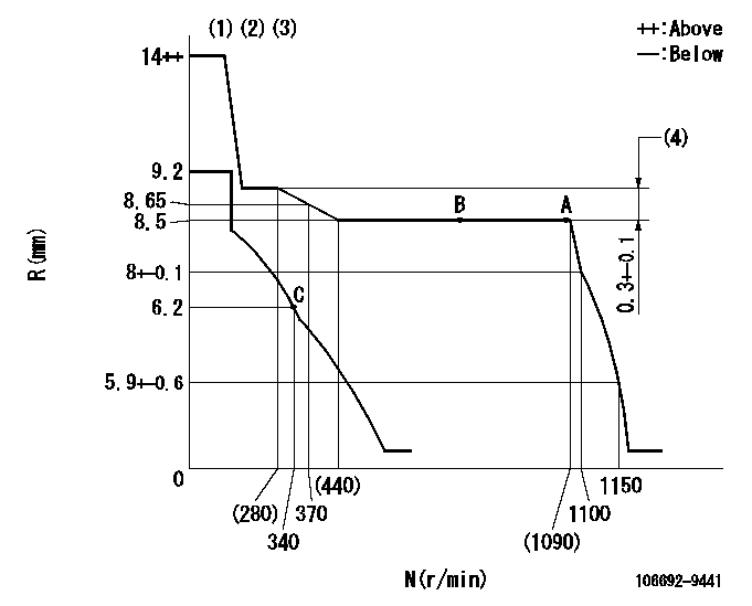
N:Pump speed
R:Rack position (mm)
(1)Target notch: K
(2)Tolerance for racks not indicated: +-0.05mm.
(3)Do not adjust boost compensator spring.
(4)Rack difference between N = N1 and N = N2
----------
K=10 N1=1050r/min N2=240r/min
----------
----------
K=10 N1=1050r/min N2=240r/min
----------
Speed control lever angle

F:Full speed
I:Idle
(1)Stopper bolt setting
----------
----------
a=9deg+-5deg b=28deg+-5deg
----------
----------
a=9deg+-5deg b=28deg+-5deg
Stop lever angle

N:Pump normal
S:Stop the pump.
(1)Rack position = aa, speed = bb (stamp at delivery)
----------
aa=1-0.5mm bb=0r/min
----------
a=33deg+-5deg b=70deg+-5deg
----------
aa=1-0.5mm bb=0r/min
----------
a=33deg+-5deg b=70deg+-5deg
Timing setting

(1)Pump vertical direction
(2)Coupling's key groove position at No 1 cylinder's beginning of injection
(3)-
(4)-
----------
----------
a=(150deg)
----------
----------
a=(150deg)
Information:
Table 1
Revision Summary of Changes
01 Updated the effectivity. A new Diesel Exhaust Fluid (DEF) filter is now available on machines listed above. The DEF filter has an improved filter efficiency.
Do not operate or work on this product unless you have read and understood the instruction and warnings in the relevant Operation and Maintenance Manuals and relevant service literature. Failure to follow the instructions or heed the warnings could result in injury or death. Proper care is your responsibility.
The following changes are now available for the products within the listed serial numbers.Refer to Table 2 for a list of a new and former part numbers.
Table 2
Required Parts
DEF Filter DEF Manifold Group
Application New Part Number Part Name Former Part Number (1) New Part Number Part Name Former Part Number (1)
785G 584-8139 DEF Filter 453-1607 585-3956 DEF Manifold Gp 480-4090
789G, 793F, 794AC, 797F, and 994K 584-8140 DEF Filter 453-1608 585-3957 DEF Manifold Gp 480-4091
(1) The former part number listed is for reference only and may differ.Note: The new DEF manifold group part numbers listed in Table 2 will be assembled with the new filters.
Illustration 1 g06570567
DEF manifold
(1) ClampAn additional change, beyond the new DEF filter, was made to the 585-3957 DEF Manifold Gp. The clamp in the location highlighted in Illustration 2 was removed to eliminate a potential wear point.
Illustration 2 g06570636
Typical view of the DEF manifold group
(2) DEF manifold
(3) DEF filterThis change is effective for the Pump Electronic Tank Unit (PETU) serial numbers listed in Table 3.
Table 3
Pump Electronic Tank Unit (PETU) Serial Numbers
S/N:PET001414J
S/N:PET001444J-UP