Information injection-pump assembly
ZEXEL
106692-9370
1066929370

Rating:
Cross reference number
ZEXEL
106692-9370
1066929370
Zexel num
Bosch num
Firm num
Name
106692-9370
INJECTION-PUMP ASSEMBLY
Calibration Data:
Adjustment conditions
Test oil
1404 Test oil ISO4113 or {SAEJ967d}
1404 Test oil ISO4113 or {SAEJ967d}
Test oil temperature
degC
40
40
45
Nozzle and nozzle holder
105780-8140
Bosch type code
EF8511/9A
Nozzle
105780-0000
Bosch type code
DN12SD12T
Nozzle holder
105780-2080
Bosch type code
EF8511/9
Opening pressure
MPa
17.2
Opening pressure
kgf/cm2
175
Injection pipe
Outer diameter - inner diameter - length (mm) mm 8-3-600
Outer diameter - inner diameter - length (mm) mm 8-3-600
Overflow valve
131424-1520
Overflow valve opening pressure
kPa
157
123
191
Overflow valve opening pressure
kgf/cm2
1.6
1.25
1.95
Tester oil delivery pressure
kPa
157
157
157
Tester oil delivery pressure
kgf/cm2
1.6
1.6
1.6
Direction of rotation (viewed from drive side)
Right R
Right R
Injection timing adjustment
Direction of rotation (viewed from drive side)
Right R
Right R
Injection order
1-4-2-6-
3-5
Pre-stroke
mm
2.9
2.85
2.95
Beginning of injection position
Drive side NO.1
Drive side NO.1
Difference between angles 1
Cal 1-4 deg. 60 59.5 60.5
Cal 1-4 deg. 60 59.5 60.5
Difference between angles 2
Cyl.1-2 deg. 120 119.5 120.5
Cyl.1-2 deg. 120 119.5 120.5
Difference between angles 3
Cal 1-6 deg. 180 179.5 180.5
Cal 1-6 deg. 180 179.5 180.5
Difference between angles 4
Cal 1-3 deg. 240 239.5 240.5
Cal 1-3 deg. 240 239.5 240.5
Difference between angles 5
Cal 1-5 deg. 300 299.5 300.5
Cal 1-5 deg. 300 299.5 300.5
Injection quantity adjustment
Adjusting point
A
Rack position
13
Pump speed
r/min
900
900
900
Each cylinder's injection qty
mm3/st.
236
231.3
240.7
Basic
*
Fixing the rack
*
Injection quantity adjustment_02
Adjusting point
B
Rack position
5.8+-0.5
Pump speed
r/min
200
200
200
Each cylinder's injection qty
mm3/st.
32.5
28.3
36.7
Fixing the rack
*
Test data Ex:
Governor adjustment
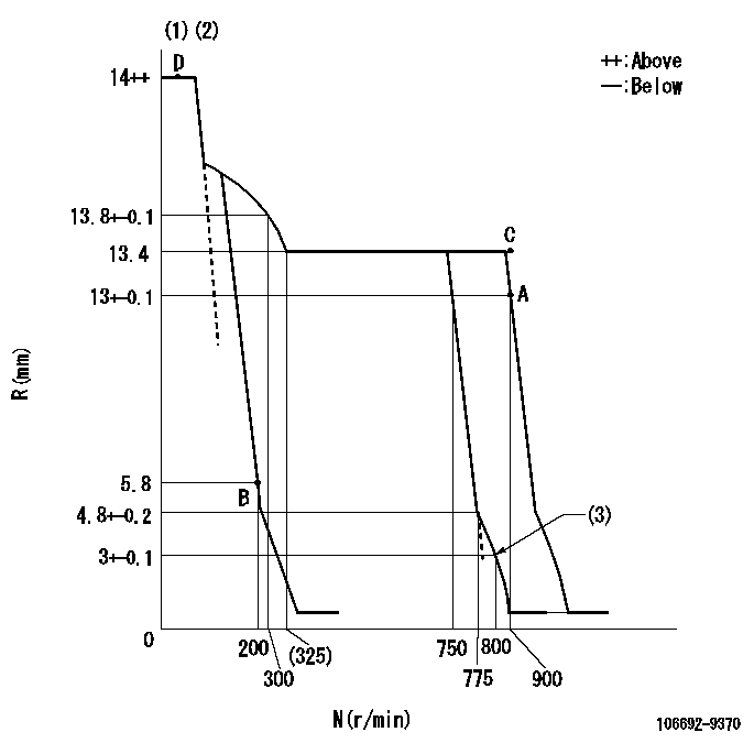
N:Pump speed
R:Rack position (mm)
(1)Target notch: K
(2)Tolerance for racks not indicated: +-0.05mm.
(3)Set idle sub-spring
----------
K=5
----------
----------
K=5
----------
Speed control lever angle
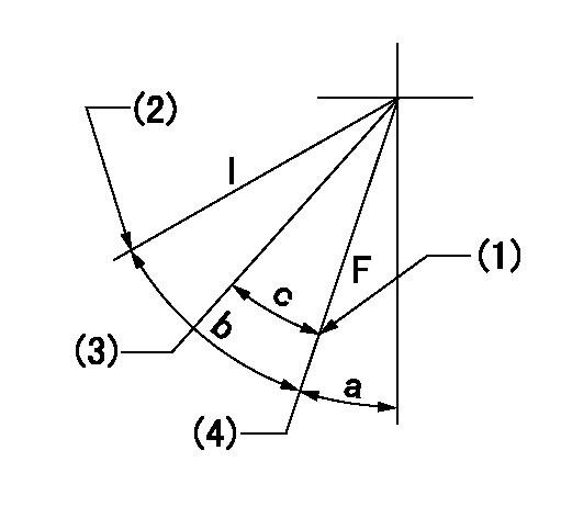
F:Full speed
I:Idle
(1)Stopper bolt setting
(2)Stopper bolt setting
(3)When pump speed set at aa
(4)Set the pump speed at bb.
----------
aa=750r/min bb=900r/min
----------
a=23deg+-5deg b=29deg+-5deg c=6deg+-5deg
----------
aa=750r/min bb=900r/min
----------
a=23deg+-5deg b=29deg+-5deg c=6deg+-5deg
Stop lever angle
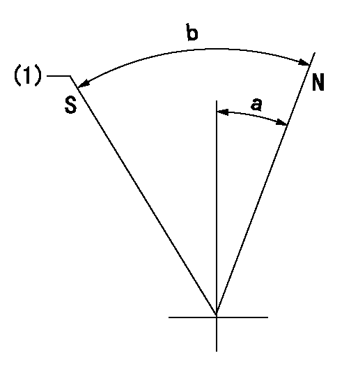
N:Pump normal
S:Stop the pump.
(1)Rack position aa or less, pump speed bb
----------
aa=5.3mm bb=0r/min
----------
a=20deg+-5deg b=53deg+-5deg
----------
aa=5.3mm bb=0r/min
----------
a=20deg+-5deg b=53deg+-5deg
Timing setting

(1)Pump vertical direction
(2)Position of camshaft's key groove at No 1 cylinder's beginning of injection
(3)-
(4)-
----------
----------
a=(50deg)
----------
----------
a=(50deg)
Information:
Hot Test Procedure
Start engine, run at low idle, and ensure minimum oil pressure of 235 kPa (34 psi) is present within 30 sec. Walk around the engine and check for leaks. Run straight diesel with Natural Gas shut off.
Check ET for Codes.
Run Break-In 1 Speed and Load for 1 min.
Break-In load and speed 2967 Nm at 1440 rpm.
Cycle Load Between Break-In 2 Load, and Break-In 1 Load, 3 times holding at each load for 30 sec.
Break-In load and speed 5933 Nm at 1800 rpm.
Remove dyno load and go to Low Idle.
Illustration 276 g06547946
Cat ET EGR system test
Run EGR verification check in ET, and ensure it Passes. Run the EGR verification check a second time if the first one fails. If itfailsagain shut the engine offand troubleshoot EGR system.
Cat ET EGR System Test.
If Aftertreatment is not installed the Exhaust Backpressure must be within pressure tolerance of 7 3 kPa (1.0 0.4 psi) at the end of Break-In 2.
Illustration 277 g06547948
Cat ET fuel system functional test
Run Fuel System verification check in ET, and ensure it Passes.Note: Checking to see, if this is needed or not
DO NOT Lug engine until the engine has a successful EGR verification check, and Engine Backpressure is acceptable (Aftertreatment installed or backpressure verified during Break-In 2).
Set engine speed to Hi Idle speed.
Lug to engine to "Full Load speed" and allow water temps to stabilize.
EJW 85° 4°C (185° 39°F).
SCAC 46° 3°C (115° 37°F).
ATAAC Out 48° 3°C (118° 37°F).
Acquire "Full Load Data".
Take screenshot from ET for some ECM parameters.
Lug engine to "Torque Check" speed and allow engine to stabilize.
Acquire "Torque Check Data".
Take screenshot from ET for some ECM parameters.
Go to "Gas Blending Speed and Load".
754 bkW at 1800 rpm.
Turn on Gas supply. Natural Gas supply pressure measured on engine should be between 100 70 kPa (15 to 10 psi).
Let engine stabilize for 1 min.
Acquire Diesel and Natural Gas fuel rates.
Take ET screenshot.
Remove engine load and stabilize at High Idle speed for 1 min.
Acquire Hi Idle Data.
Take screenshot from ET for some ECM parameters.
Set engine to Low Idle speed and stabilize for 1 min.
Acquire Low Idle Data.
Take screenshot from ET for some ECM parameters.Nominal Test Values
The following nominal value information for hot tests can be referenced in the TMI system under the following test specs:
Illustration 278 g06547949
TMI Spec Summary
Illustration 279 g06547950
Full Load Point Values (2500 hp SCAC)
Illustration 280 g06547951
Full Load Point Values (2500 hp ATAAC)
Full Load Point.
Illustration 281 g06547952
Torque Check Point Values (2500 hp SCAC)
Illustration 282 g06547953
Torque Check Point Values (2500 hp ATAAC)
Torque Check Point.
Illustration 283 g06547954
Gas Blend Point Values (2500 hp SCAC)
Illustration 284 g06547955
Gas Blend Point Values (2500 hp ATAAC)
Gas Blend Point.
Have questions with 106692-9370?
Group cross 106692-9370 ZEXEL
Komatsu
Komatsu
Komatsu
Yanmar
Yanmar
Yanmar
Yanmar
Komatsu
Komatsu
Komatsu
106692-9370
INJECTION-PUMP ASSEMBLY