Information injection-pump assembly
BOSCH
9 400 611 002
9400611002
ZEXEL
106692-9301
1066929301
Rating:
Service parts 106692-9301 INJECTION-PUMP ASSEMBLY:
1.
_

5.
AUTOM. ADVANCE MECHANIS
7.
COUPLING PLATE
8.
_
9.
_
11.
Nozzle and Holder
6151-12-3200
12.
Open Pre:MPa(Kqf/cm2)
24.5{250}
15.
NOZZLE SET
Include in #1:
106692-9301
as INJECTION-PUMP ASSEMBLY
Cross reference number
BOSCH
9 400 611 002
9400611002
ZEXEL
106692-9301
1066929301
Zexel num
Bosch num
Firm num
Name
Calibration Data:
Adjustment conditions
Test oil
1404 Test oil ISO4113 or {SAEJ967d}
1404 Test oil ISO4113 or {SAEJ967d}
Test oil temperature
degC
40
40
45
Nozzle and nozzle holder
105780-8140
Bosch type code
EF8511/9A
Nozzle
105780-0000
Bosch type code
DN12SD12T
Nozzle holder
105780-2080
Bosch type code
EF8511/9
Opening pressure
MPa
17.2
Opening pressure
kgf/cm2
175
Injection pipe
Outer diameter - inner diameter - length (mm) mm 8-3-600
Outer diameter - inner diameter - length (mm) mm 8-3-600
Overflow valve
131424-1520
Overflow valve opening pressure
kPa
157
123
191
Overflow valve opening pressure
kgf/cm2
1.6
1.25
1.95
Tester oil delivery pressure
kPa
157
157
157
Tester oil delivery pressure
kgf/cm2
1.6
1.6
1.6
Direction of rotation (viewed from drive side)
Left L
Left L
Injection timing adjustment
Direction of rotation (viewed from drive side)
Left L
Left L
Injection order
1-5-3-6-
2-4
Pre-stroke
mm
3.75
3.7
3.8
Beginning of injection position
Drive side NO.1
Drive side NO.1
Difference between angles 1
Cal 1-5 deg. 60 59.5 60.5
Cal 1-5 deg. 60 59.5 60.5
Difference between angles 2
Cal 1-3 deg. 120 119.5 120.5
Cal 1-3 deg. 120 119.5 120.5
Difference between angles 3
Cal 1-6 deg. 180 179.5 180.5
Cal 1-6 deg. 180 179.5 180.5
Difference between angles 4
Cyl.1-2 deg. 240 239.5 240.5
Cyl.1-2 deg. 240 239.5 240.5
Difference between angles 5
Cal 1-4 deg. 300 299.5 300.5
Cal 1-4 deg. 300 299.5 300.5
Injection quantity adjustment
Adjusting point
A
Rack position
9.1
Pump speed
r/min
650
650
650
Average injection quantity
mm3/st.
144
142
146
Max. variation between cylinders
%
0
-3
3
Basic
*
Fixing the lever
*
Boost pressure
kPa
30.7
30.7
Boost pressure
mmHg
230
230
Injection quantity adjustment_02
Adjusting point
C
Rack position
6.4+-0.5
Pump speed
r/min
325
325
325
Average injection quantity
mm3/st.
8.5
7
10
Max. variation between cylinders
%
0
-15
15
Fixing the rack
*
Boost pressure
kPa
0
0
0
Boost pressure
mmHg
0
0
0
Injection quantity adjustment_03
Adjusting point
E
Rack position
-
Pump speed
r/min
100
100
100
Average injection quantity
mm3/st.
155
145
165
Fixing the lever
*
Boost pressure
kPa
0
0
0
Boost pressure
mmHg
0
0
0
Rack limit
*
Boost compensator adjustment
Pump speed
r/min
600
600
600
Rack position
R1-0.2
Boost pressure
kPa
14.7
12
17.4
Boost pressure
mmHg
110
90
130
Boost compensator adjustment_02
Pump speed
r/min
600
600
600
Rack position
R1(9.1)
Boost pressure
kPa
17.3
17.3
17.3
Boost pressure
mmHg
130
130
130
Test data Ex:
Governor adjustment
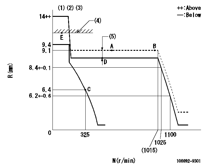
N:Pump speed
R:Rack position (mm)
(1)Target notch: K
(2)Tolerance for racks not indicated: +-0.05mm.
(3)The torque control spring does not operate.
(4)RACK LIMIT
(5)Boost compensator stroke: BCL
----------
K=18 BCL=0.2+-0.1mm
----------
----------
K=18 BCL=0.2+-0.1mm
----------
Speed control lever angle
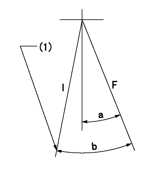
F:Full speed
I:Idle
(1)Stopper bolt setting
----------
----------
a=8deg+-5deg b=20deg+-5deg
----------
----------
a=8deg+-5deg b=20deg+-5deg
Stop lever angle
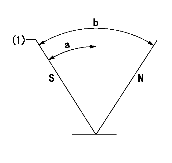
N:Pump normal
S:Stop the pump.
(1)Pump speed aa and rack position bb (to be sealed at delivery)
----------
aa=0r/min bb=1-0.5mm
----------
a=33deg+-5deg b=70deg+-5deg
----------
aa=0r/min bb=1-0.5mm
----------
a=33deg+-5deg b=70deg+-5deg
Timing setting

(1)Pump vertical direction
(2)Coupling's key groove position at No 1 cylinder's beginning of injection
(3)-
(4)-
----------
----------
a=(150deg)
----------
----------
a=(150deg)
Information:
Do not operate or work on this product unless you have read and understood the instruction and warnings in the relevant Operation and Maintenance Manuals and relevant service literature. Failure to follow the instructions or heed the warnings could result in injury or death. Proper care is your responsibility.
Illustration 1 g06407782
(1) Nut
(2) Nut
(3) Connectors
Ensure that the connectors (3) sealing surfaces are clean. Ensure that connectors (3) has only one O-ring.
Tighten connectors (3) to 105 10 N m (77 7 lb ft).
On all engines, use the 5P-0329 Crowfoot Flare-Nut Wrench to tighten the fuel injection line nut (1).
On engines that use heavy fuel oil; use the 5P-0328 Crowfoot Flare-Nut Wrench to tighten the fuel injector tip coolant line nut (2).