Information injection-pump assembly
ZEXEL
106692-9260
1066929260
KOMATSU
6151721770
6151721770
Rating:
Service parts 106692-9260 INJECTION-PUMP ASSEMBLY:
1.
_
5.
AUTOM. ADVANCE MECHANIS
8.
_
9.
_
11.
Nozzle and Holder
6151-12-3200
12.
Open Pre:MPa(Kqf/cm2)
24.5{250}
15.
NOZZLE SET
Include in #1:
106692-9260
as INJECTION-PUMP ASSEMBLY
Cross reference number
ZEXEL
106692-9260
1066929260
KOMATSU
6151721770
6151721770
Zexel num
Bosch num
Firm num
Name
Calibration Data:
Adjustment conditions
Test oil
1404 Test oil ISO4113 or {SAEJ967d}
1404 Test oil ISO4113 or {SAEJ967d}
Test oil temperature
degC
40
40
45
Nozzle and nozzle holder
105780-8140
Bosch type code
EF8511/9A
Nozzle
105780-0000
Bosch type code
DN12SD12T
Nozzle holder
105780-2080
Bosch type code
EF8511/9
Opening pressure
MPa
17.2
Opening pressure
kgf/cm2
175
Injection pipe
Outer diameter - inner diameter - length (mm) mm 8-3-600
Outer diameter - inner diameter - length (mm) mm 8-3-600
Overflow valve
131424-1520
Overflow valve opening pressure
kPa
157
123
191
Overflow valve opening pressure
kgf/cm2
1.6
1.25
1.95
Tester oil delivery pressure
kPa
157
157
157
Tester oil delivery pressure
kgf/cm2
1.6
1.6
1.6
Direction of rotation (viewed from drive side)
Left L
Left L
Injection timing adjustment
Direction of rotation (viewed from drive side)
Left L
Left L
Injection order
1-5-3-6-
2-4
Pre-stroke
mm
3.75
3.7
3.8
Beginning of injection position
Drive side NO.1
Drive side NO.1
Difference between angles 1
Cal 1-5 deg. 60 59.5 60.5
Cal 1-5 deg. 60 59.5 60.5
Difference between angles 2
Cal 1-3 deg. 120 119.5 120.5
Cal 1-3 deg. 120 119.5 120.5
Difference between angles 3
Cal 1-6 deg. 180 179.5 180.5
Cal 1-6 deg. 180 179.5 180.5
Difference between angles 4
Cyl.1-2 deg. 240 239.5 240.5
Cyl.1-2 deg. 240 239.5 240.5
Difference between angles 5
Cal 1-4 deg. 300 299.5 300.5
Cal 1-4 deg. 300 299.5 300.5
Injection quantity adjustment
Adjusting point
A
Rack position
9.1
Pump speed
r/min
1000
1000
1000
Average injection quantity
mm3/st.
121
119
123
Max. variation between cylinders
%
0
-3
3
Basic
*
Fixing the lever
*
Boost pressure
kPa
31.3
31.3
Boost pressure
mmHg
235
235
Injection quantity adjustment_02
Adjusting point
D
Rack position
6+-0.5
Pump speed
r/min
470
470
470
Average injection quantity
mm3/st.
15
13.5
16.5
Max. variation between cylinders
%
0
-15
15
Fixing the rack
*
Boost pressure
kPa
0
0
0
Boost pressure
mmHg
0
0
0
Injection quantity adjustment_03
Adjusting point
F
Rack position
12.5+-0.
1
Pump speed
r/min
100
100
100
Average injection quantity
mm3/st.
195
175
215
Fixing the lever
*
Boost pressure
kPa
0
0
0
Boost pressure
mmHg
0
0
0
Rack limit
*
Boost compensator adjustment
Pump speed
r/min
600
600
600
Rack position
R1-1
Boost pressure
kPa
7.3
4.6
10
Boost pressure
mmHg
55
35
75
Boost compensator adjustment_02
Pump speed
r/min
600
600
600
Rack position
R1(9.3)
Boost pressure
kPa
18
11.3
24.7
Boost pressure
mmHg
135
85
185
Test data Ex:
Governor adjustment
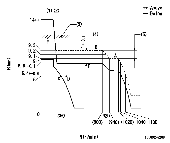
N:Pump speed
R:Rack position (mm)
(1)Target notch: K
(2)Tolerance for racks not indicated: +-0.05mm.
(3)RACK LIMIT: RAL
(4)Boost compensator stroke
(5)Rack difference between N = N1 and N = N2
----------
K=7 RAL=12.5+-0.1mm N1=1000r/min N2=700r/min
----------
----------
K=7 RAL=12.5+-0.1mm N1=1000r/min N2=700r/min
----------
Speed control lever angle
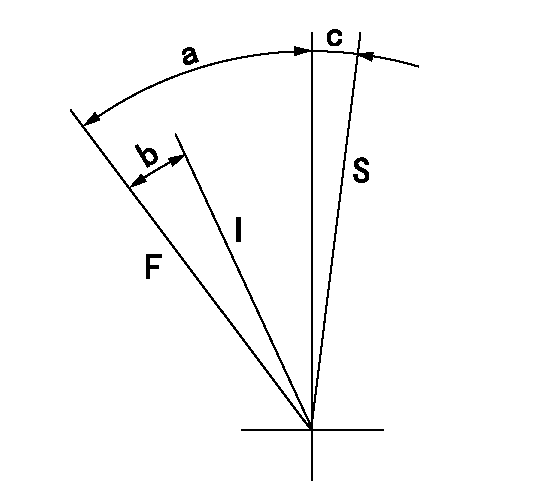
F:Full speed
I:Idle
S:Stop
----------
----------
a=30deg+-5deg b=21deg+-5deg c=3deg+-3deg
----------
----------
a=30deg+-5deg b=21deg+-5deg c=3deg+-3deg
0000001501 LEVER
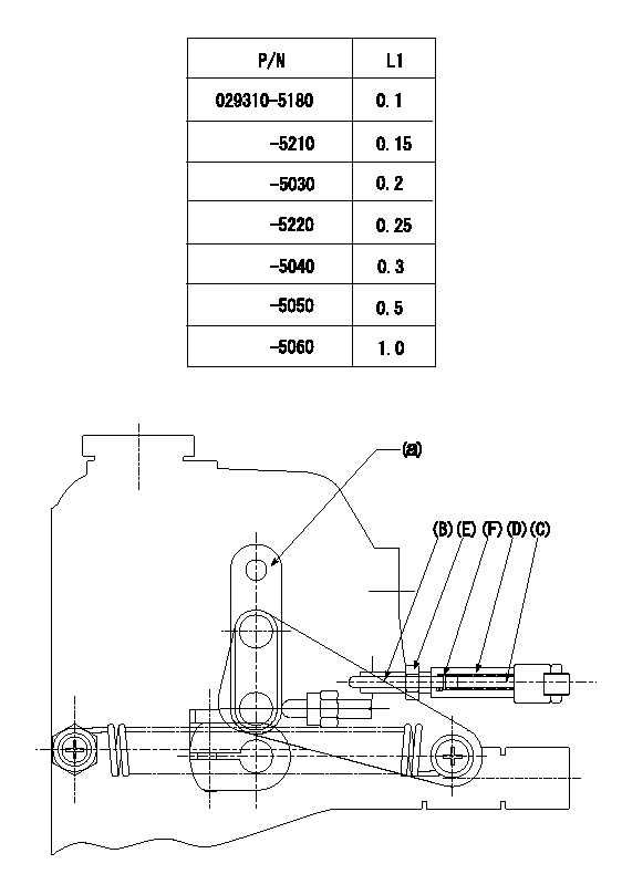
Speed lever adjustment
1. (1) For idling hold the speed lever (a) against the push rod (B).
(2)At this time, confirm that the spring (C) is not bent by the operating torque of the speed lever.
2. (1) To stop, bend the spring (C) using the speed lever.
(2)Set so that the rack position is L2.
(3)Set and fix using lock nut (E) so that it contacts the guide screw (D).
(4)Adjust rack position at this time using shim (F).
3. Confirm that the speed lever returns to the idling position when pulled in the stop direction and then released.
----------
L2=0.2~2mm
----------
----------
L2=0.2~2mm
----------
Timing setting
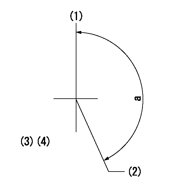
(1)Pump vertical direction
(2)Coupling's key groove position at No 1 cylinder's beginning of injection
(3)-
(4)-
----------
----------
a=(150deg)
----------
----------
a=(150deg)
Information:
Illustration 9 g06286243
Typical example
Illustration 9 shows the governor plate displaying high wear at the sleeve contact points.
Illustration 10 g06286261
Typical example
Illustration 8 shows the thrust sleeve displaying an excessive wear groove.
Illustration 11 g06286627
Typical example
Illustration 12 g06286629
Typical example
Illustration 11 and Illustration 11 show the weight thrust fingers badly worn.
Illustration 13 g06286630
Typical example
Illustration 13 shows pivot heels showing excessive wear.Fuel Quality
Illustration 14 g06286604
Typical example
Illustration 14 shows that nitrile rubber seals have cracked causing fuel leakage. The cracks in the seals are attributed to fuel attacking the rubber. Ensure that there is no particle contamination in the fuel injection pump.Unmodified Vegetable Oil or Poor Quality FAME
Illustration 15 g06286612
Typical example
Stuck metering valve causing engine overspeed. Top cover of fuel injection pump removed. Black sticky material adhering to all non-alloy surfaces, this is due to the use of unmodified vegetable oil or poor quality FAME. Refer to Illustration 15.High Water Content in Fuel
Illustration 16 g06286613
Typical example
Illustration 17 g06286615
Typical example
Illustration 16 and Illustration 17 show corrosion on component surfaces, due to high water content in fuel.Characteristics Associated with Poor Quality Fuel and Potential Issue
Table 1
Fuel Characteristics Effect Issue
FAMEs in general Causes some elastomers to soften, swell, harden, and crack. Fuel leakage.
Free methanol in FAME Corrodes aluminum and zinc. Low flash point. Corrosion on fuel injection equipment.
FAME process chemicals Potassium and sodium compound. Solid particles. Blocked nozzles.
Dissolved water in FAME Reversion of FAME to a fatty acid. Fuel filter plugging.
Free water in FAME Corrosion. Sustains bacteria. Corrosion on fuel injection equipment. Sludging.
Free glycerine, mono, and
di-glycerines in FAME Corrodes non-ferrous metals.
Sediments on moving parts and lacquering. Fuel filter clogging.
Fuel injector clogging.
Free fatty acid Corrosion of Zinc plating.
Slats of organic acids.
Organic compound formed. Corrosion on fuel injection equipment.
Fuel filter plugging.
Sediment on components
High viscosity at low temperature Generates excessive localized heat.
Higher stressed components. Fuel injection pump seizures.
Early life issues.
Poor nozzle spray.
Corrosive acids Corrodes all metallic parts. Corrosion on fuel injection equipment.
High molecular organic acids Corrosion of Zinc plating.
Slats of organic acids.
Organic compound formed. Corrosion on fuel injection equipment.
Fuel filter plugging.
Sediment on components
Polymerization products Deposits in fuel mixes Fuel filter plugging. Lacquering formation in hot areas. Recommended Procedures
Prime the fuel system to remove any air. Refer to Operation and Maintenance Manual, Fuel System - Prime for the correct procedure.Check the pressure of the fuel system. Refer to Systems Operation, Testing and Adjusting, Fuel System Pressure - Test for the correct procedure.Check the operation of the fuel injection nozzles. Refer to Systems Operation, Testing and Adjusting, Fuel Injection Nozzle - Test for the correct procedure.To inspect the fuel injection pump, refer to Special Instruction, REHS3767, Inspection of Fuel Injection Pumps on 3054C, C3.3, C4.4 (Mechanical), and C7.1 (Mechanical) Engines for the correct procedure.