Information injection-pump assembly
ZEXEL
106692-4620
1066924620

Rating:
Cross reference number
ZEXEL
106692-4620
1066924620
Zexel num
Bosch num
Firm num
Name
Calibration Data:
Adjustment conditions
Test oil
1404 Test oil ISO4113 or {SAEJ967d}
1404 Test oil ISO4113 or {SAEJ967d}
Test oil temperature
degC
40
40
45
Nozzle and nozzle holder
105780-8130
Bosch type code
EFEP215A
Nozzle
105780-0050
Bosch type code
DN6TD119NP1T
Nozzle holder
105780-2090
Bosch type code
EFEP215
Opening pressure
MPa
17.2
Opening pressure
kgf/cm2
175
Injection pipe
Outer diameter - inner diameter - length (mm) mm 8-3-600
Outer diameter - inner diameter - length (mm) mm 8-3-600
Tester oil delivery pressure
kPa
157
157
157
Tester oil delivery pressure
kgf/cm2
1.6
1.6
1.6
Direction of rotation (viewed from drive side)
Left L
Left L
Injection timing adjustment
Direction of rotation (viewed from drive side)
Left L
Left L
Injection order
1-5-3-6-
2-4
Pre-stroke
mm
2.4
2.35
2.45
Beginning of injection position
Drive side NO.1
Drive side NO.1
Difference between angles 1
Cal 1-5 deg. 60 59.5 60.5
Cal 1-5 deg. 60 59.5 60.5
Difference between angles 2
Cal 1-3 deg. 120 119.5 120.5
Cal 1-3 deg. 120 119.5 120.5
Difference between angles 3
Cal 1-6 deg. 180 179.5 180.5
Cal 1-6 deg. 180 179.5 180.5
Difference between angles 4
Cyl.1-2 deg. 240 239.5 240.5
Cyl.1-2 deg. 240 239.5 240.5
Difference between angles 5
Cal 1-4 deg. 300 299.5 300.5
Cal 1-4 deg. 300 299.5 300.5
Injection quantity adjustment
Adjusting point
A
Rack position
9.7
Pump speed
r/min
1000
1000
1000
Each cylinder's injection qty
mm3/st.
245.8
238.8
252.8
Basic
*
Fixing the lever
*
Injection quantity adjustment_02
Adjusting point
B
Rack position
10.2
Pump speed
r/min
700
700
700
Average injection quantity
mm3/st.
252.7
247.7
257.7
Fixing the lever
*
Injection quantity adjustment_03
Adjusting point
C
Rack position
5.9+-0.5
Pump speed
r/min
325
325
325
Average injection quantity
mm3/st.
27.7
22.7
32.7
Max. variation between cylinders
%
0
-10
10
Fixing the rack
*
Injection quantity adjustment_04
Adjusting point
D
Rack position
-
Pump speed
r/min
100
100
100
Average injection quantity
mm3/st.
200
190
210
Fixing the lever
*
Rack limit
*
Test data Ex:
Governor adjustment
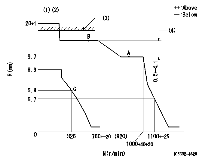
N:Pump speed
R:Rack position (mm)
(1)Target notch: K
(2)Tolerance for racks not indicated: +-0.05mm.
(3)RACK LIMIT
(4)Rack difference between N = N1 and N = N2
----------
K=15 N1=1000r/min N2=700r/min
----------
----------
K=15 N1=1000r/min N2=700r/min
----------
Speed control lever angle
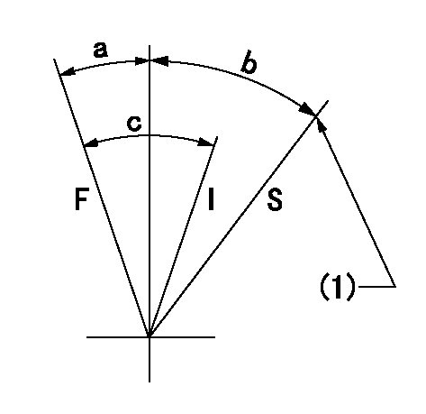
F:Full speed
I:Idle
S:Stop
(1)Stopper bolt setting
----------
----------
a=17deg+-5deg b=32deg+-3deg c=31deg+-5deg
----------
----------
a=17deg+-5deg b=32deg+-3deg c=31deg+-5deg
0000001501 LEVER
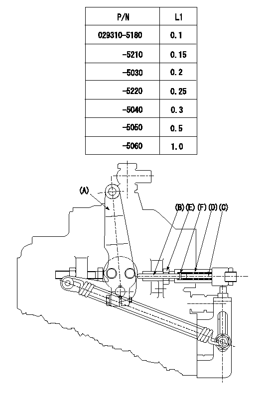
Speed lever adjustment
1. (1) For idling hold the speed lever (a) against the push rod (B).
(2)At this time, confirm that the spring (C) is not bent by the operating torque of the speed lever.
2. (1) To stop, bend the spring (C) using the speed lever.
(2)Position the rack at L2. (Adjustment is performed using the shim (F).)
(3)Set and fix using lock nut (E) so that it contacts the guide screw (D).
3. Confirm that the speed lever returns to the idling position when pulled in the stop direction and then released.
----------
L2=0.2~2mm
----------
----------
L2=0.2~2mm
----------
Timing setting

(1)Pump vertical direction
(2)Position of spline gear's aligning mark at No 1 cylinder's beginning of injection (key position)
(3)-
(4)-
----------
----------
a=(130deg)
----------
----------
a=(130deg)
Information:
Introduction
The problem that is identified below does not have a known permanent solution. Until a permanent solution is known, use the solution that is identified below.Problem
The diesel exhaust fluid (DEF) quality sensors are susceptible to seeing the following fault codes.
Table 1
J1939 CDL Code Description
3516-2 3100-2 Aftertreatment #1 DEF Concentration: Erratic, Intermittent or Incorrect
3516-12 3100-12 Aftertreatment #1 DEF Concentration: Failure
3516-16 E1365 High Aftertreatment #1 DEF Concentration
3516-18 E1364 Low Aftertreatment #1 DEF Concentration Solution
The latest software available in SIS has improvements in it related to the DEF quality sensor and these fault codes.
Ensure that the latest engine and aftertreatment software is installed prior to any hardware replacements.
Ensure that the latest DCU software is installed ( 539-3577 Engine Software (24V DCU) or 539-3576 Engine Software (12V DCU)).
In addition to the troubleshooting for these fault codes in SIS web, ensure that DEF quality is checked with both a refractometer and the 466-8796 Test Strips as outlined in Diesel Exhaust Fluid Quality - Test procedure in SIS.
Keep the DEF tank full when machine/engine will not be operated for an extended period of time to help reduce manifold exposure to ammonia gases in the DEF tank.Have seen cases of contamination where the test strips will not detect it if contamination is not hydrocarbon-based. In these instances, the DEF will appear to be cloudy when doing a visual comparison to a good, clean DEF sample.While working through issues related to these particular fault codes, email Blunier_Derek_W to provide troubleshooting information and documentation as to what was found.Information to Provide
PSRPT with histograms
Application History File
All troubleshooting resultsIf the DEF manifold does get replaced, provide the following:
Dealer code
Workorder number
Serial number
Hours at repair
DEF sample collected from top level of tank to be returned along with the DEF manifoldA Send It Back (SIB) will be created to get the DEF manifold returned.Downloading an Application History File
Illustration 1 g06233931
Click the appropriate ECM.
Click "Information".
Click "Warranty Report".
Illustration 2 g06233935
Click "ECM Information".
Click the "Yes" button.
Illustration 3 g06233938
Click "Additional Service".
Click the "Save" button.