Information injection-pump assembly
ZEXEL
106692-4610
1066924610

Rating:
Cross reference number
ZEXEL
106692-4610
1066924610
Zexel num
Bosch num
Firm num
Name
Calibration Data:
Adjustment conditions
Test oil
1404 Test oil ISO4113 or {SAEJ967d}
1404 Test oil ISO4113 or {SAEJ967d}
Test oil temperature
degC
40
40
45
Nozzle and nozzle holder
105780-8130
Bosch type code
EFEP215A
Nozzle
105780-0050
Bosch type code
DN6TD119NP1T
Nozzle holder
105780-2090
Bosch type code
EFEP215
Opening pressure
MPa
17.2
Opening pressure
kgf/cm2
175
Injection pipe
Outer diameter - inner diameter - length (mm) mm 8-3-600
Outer diameter - inner diameter - length (mm) mm 8-3-600
Tester oil delivery pressure
kPa
157
157
157
Tester oil delivery pressure
kgf/cm2
1.6
1.6
1.6
Direction of rotation (viewed from drive side)
Left L
Left L
Injection timing adjustment
Direction of rotation (viewed from drive side)
Left L
Left L
Injection order
1-5-3-6-
2-4
Pre-stroke
mm
2.4
2.35
2.45
Beginning of injection position
Drive side NO.1
Drive side NO.1
Difference between angles 1
Cal 1-5 deg. 60 59.5 60.5
Cal 1-5 deg. 60 59.5 60.5
Difference between angles 2
Cal 1-3 deg. 120 119.5 120.5
Cal 1-3 deg. 120 119.5 120.5
Difference between angles 3
Cal 1-6 deg. 180 179.5 180.5
Cal 1-6 deg. 180 179.5 180.5
Difference between angles 4
Cyl.1-2 deg. 240 239.5 240.5
Cyl.1-2 deg. 240 239.5 240.5
Difference between angles 5
Cal 1-4 deg. 300 299.5 300.5
Cal 1-4 deg. 300 299.5 300.5
Injection quantity adjustment
Adjusting point
A
Rack position
11.2
Pump speed
r/min
1000
1000
1000
Each cylinder's injection qty
mm3/st.
297
291.3
302.7
Basic
*
Fixing the lever
*
Boost pressure
kPa
61.3
61.3
Boost pressure
mmHg
460
460
Injection quantity adjustment_02
Adjusting point
B
Rack position
11.4
Pump speed
r/min
700
700
700
Average injection quantity
mm3/st.
310
305
315
Fixing the lever
*
Boost pressure
kPa
61.3
61.3
Boost pressure
mmHg
460
460
Injection quantity adjustment_03
Adjusting point
C
Rack position
5.9+-0.5
Pump speed
r/min
325
325
325
Average injection quantity
mm3/st.
27.7
22.7
32.7
Max. variation between cylinders
%
0
-10
10
Fixing the rack
*
Boost pressure
kPa
0
0
0
Boost pressure
mmHg
0
0
0
Injection quantity adjustment_04
Adjusting point
E
Rack position
11.6++
Pump speed
r/min
100
100
100
Average injection quantity
mm3/st.
245
235
255
Fixing the lever
*
Boost pressure
kPa
0
0
0
Boost pressure
mmHg
0
0
0
Rack limit
*
Boost compensator adjustment
Pump speed
r/min
400
400
400
Rack position
R1-1.9
Boost pressure
kPa
24
22.7
26.7
Boost pressure
mmHg
180
170
200
Boost compensator adjustment_02
Pump speed
r/min
400
400
400
Rack position
R1(11.4)
Boost pressure
kPa
48
41.3
54.7
Boost pressure
mmHg
360
310
410
Test data Ex:
Governor adjustment
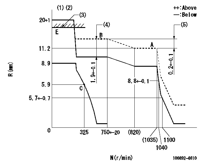
N:Pump speed
R:Rack position (mm)
(1)Target notch: K
(2)Tolerance for racks not indicated: +-0.05mm.
(3)RACK LIMIT
(4)Boost compensator stroke
(5)Rack difference between N = N1 and N = N2
----------
K=15 N1=1000r/min N2=700r/min
----------
----------
K=15 N1=1000r/min N2=700r/min
----------
Speed control lever angle
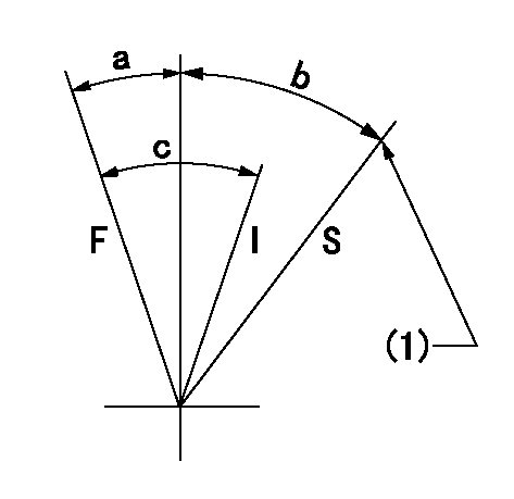
F:Full speed
I:Idle
S:Stop
(1)Stopper bolt setting
----------
----------
a=17deg+-5deg b=32deg+-3deg c=31deg+-5deg
----------
----------
a=17deg+-5deg b=32deg+-3deg c=31deg+-5deg
0000001501 LEVER
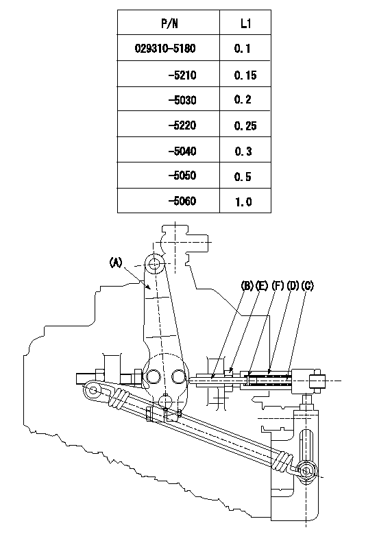
Speed lever adjustment
1. (1) For idling hold the speed lever (a) against the push rod (B).
(2)At this time, confirm that the spring (C) is not bent by the operating torque of the speed lever.
2. (1) To stop, bend the spring (C) using the speed lever.
(2)Position the rack at L2. (Adjustment is performed using the shim (F).)
(3)Set and fix using lock nut (E) so that it contacts the guide screw (D).
3. Confirm that the speed lever returns to the idling position when pulled in the stop direction and then released.
----------
L2=0.2~2mm
----------
----------
L2=0.2~2mm
----------
Timing setting

(1)Pump vertical direction
(2)Center position of spline gear's aligning tooth at No 1 cylinder's beginning of injection
(3)-
(4)-
----------
----------
a=(140deg)
----------
----------
a=(140deg)
Information:
Illustration 5 g06198951
70-Pin connector
(5) Pin 4
(6) Pin 24
Illustration 6 g06198953
40-Pin connector
(7) Pin 4
(8) Pin 24
Using the appropriate terminal extraction tool, remove the red and black wires from positions 4 and 24 of the connector. Refer to Illustration 5 and 6.
Route the extracted wires out of the engine harness and insert the wires into 3E-3370 Connector Receptacle As supplied with 517-0586 Engine Harness As. Red wire in position 1 and Black wire in position 2.Note: Minor cutting of the boot may be required.
Install the Red wire from 517-0586 Engine Harness As into position 4 of the Machine Interface Connector and install the Black wire into position 24 of the connector.
Illustration 7 g06237613
70 Pin Harness
(A) Pin 4 From Machine Interface Harness Connector
(B) Pin 24 From Machine Interface Harness Connector
(C) Pyrometer Harness Interface Connector
(D) Machine Interface Connector
Illustration 8 g06237606
40 Pin Harness
(A) Pin 4 From Machine Interface Harness Connector
(B) Pin 24 From Machine Interface Harness Connector
(E) Flying Power Leads from 514-3813 Harness As to 2 Pin Connector
(F) Machine Interface Connector
If the Pyrometer Interface Harness connector is a 70 pin, Route 517-0586 Engine Harness As to the Pyrometer Harness Interface connector and install Red wire into position 70 and the Black wire into position 69. If the Pyrometer Interface Harness connector is a 40 pin, install the Red wire into pin 1 of a 2-pin receptacle and the Black wire into pin 2. This connector will then connect to G-C3 of 514-3813 Engine Harness As.
With the engine powered, use a digital multimeter to verify that 24V power is present at the Pyrometer Harness Interface connector.Installation of 510-4068 Electronic Control Gp (Pyrometer)
Attach 489-3081 Harness As to 510-4068 Electronic Control Gp (Pyrometer) and the Pyrometer Interface Connector. Using 489-3081 Engine Harness As as a gauge, temporarily install the module on an appropriate place as per the choice of installer.Installation of 505-1731 Engine Harness As
If the engine under test is a 16 cylinder instead of a 20 cylinder, 505-1731 Engine Harness As can be installed between 489-3081 Engine Harness As and 510-4068 Electronic Control Gp.Installation of 489-3081 Engine Harness As
Perform the following procedure to install 489-3081 Engine Harness As:
Install 504-3341 Engine Harness As on the service port connector of 489-3081 Engine Harness As.
Route 504-3341 Engine Harness As to a safe location before performing tests.Note: Attach 140-9442 "Y" Adapter Cable As in order to see all the machine ECMs. Connect 504-3341 Monitor Harness As to "Y", connect other leg to Machine Service port and the third leg to Communication Adapter.Overview and Configuration On Caterpillar Electronic Technician (Cat ET)
This section will describe the overview and configuration setting on Cat ET.Cat ET Screen - Standard View
Perform the following instructions once the system is installed:
Connect to communications adapter and launch Cat ET.
Illustration 9 g06198935
After connecting, under "Available ECM(s)" select "Digital Pyrometer #1".
Illustration 10 g06199349
(9) Status button
Select the "Status" (9) button in the toolbar and then the parameters of "Digital Pyrometer #1" will appear.
Selecting "Engine Cylinder Temperature - 1"