Information injection-pump assembly
ZEXEL
106692-4270
1066924270
KOMATSU
6151711911
6151711911
Rating:
Service parts 106692-4270 INJECTION-PUMP ASSEMBLY:
1.
_
5.
AUTOM. ADVANCE MECHANIS
8.
_
9.
_
11.
Nozzle and Holder
12.
Open Pre:MPa(Kqf/cm2)
24.5(250)
15.
NOZZLE SET
Include in #1:
106692-4270
as INJECTION-PUMP ASSEMBLY
Cross reference number
ZEXEL
106692-4270
1066924270
KOMATSU
6151711911
6151711911
Zexel num
Bosch num
Firm num
Name
Calibration Data:
Adjustment conditions
Test oil
1404 Test oil ISO4113 or {SAEJ967d}
1404 Test oil ISO4113 or {SAEJ967d}
Test oil temperature
degC
40
40
45
Nozzle and nozzle holder
105780-8140
Bosch type code
EF8511/9A
Nozzle
105780-0000
Bosch type code
DN12SD12T
Nozzle holder
105780-2080
Bosch type code
EF8511/9
Opening pressure
MPa
17.2
Opening pressure
kgf/cm2
175
Injection pipe
Outer diameter - inner diameter - length (mm) mm 8-3-600
Outer diameter - inner diameter - length (mm) mm 8-3-600
Overflow valve
132424-0620
Overflow valve opening pressure
kPa
157
123
191
Overflow valve opening pressure
kgf/cm2
1.6
1.25
1.95
Tester oil delivery pressure
kPa
157
157
157
Tester oil delivery pressure
kgf/cm2
1.6
1.6
1.6
Direction of rotation (viewed from drive side)
Left L
Left L
Injection timing adjustment
Direction of rotation (viewed from drive side)
Left L
Left L
Injection order
1-5-3-6-
2-4
Pre-stroke
mm
3.75
3.7
3.8
Beginning of injection position
Drive side NO.1
Drive side NO.1
Difference between angles 1
Cal 1-5 deg. 60 59.5 60.5
Cal 1-5 deg. 60 59.5 60.5
Difference between angles 2
Cal 1-3 deg. 120 119.5 120.5
Cal 1-3 deg. 120 119.5 120.5
Difference between angles 3
Cal 1-6 deg. 180 179.5 180.5
Cal 1-6 deg. 180 179.5 180.5
Difference between angles 4
Cyl.1-2 deg. 240 239.5 240.5
Cyl.1-2 deg. 240 239.5 240.5
Difference between angles 5
Cal 1-4 deg. 300 299.5 300.5
Cal 1-4 deg. 300 299.5 300.5
Injection quantity adjustment
Adjusting point
A
Rack position
8.2
Pump speed
r/min
1050
1050
1050
Average injection quantity
mm3/st.
149.6
147.6
151.6
Max. variation between cylinders
%
0
-3
3
Basic
*
Fixing the lever
*
Injection quantity adjustment_02
Adjusting point
B
Rack position
4+-0.5
Pump speed
r/min
325
325
325
Average injection quantity
mm3/st.
12.4
10.9
13.9
Max. variation between cylinders
%
0
-15
15
Fixing the rack
*
Injection quantity adjustment_03
Adjusting point
C
Rack position
12+-0.5
Pump speed
r/min
100
100
100
Average injection quantity
mm3/st.
217
207
227
Fixing the lever
*
Rack limit
*
Test data Ex:
Governor adjustment
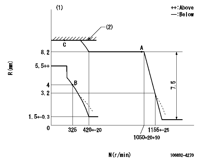
N:Pump speed
R:Rack position (mm)
(1)Damper spring setting: DL
(2)RACK LIMIT
----------
DL=3.2-0.5mm
----------
----------
DL=3.2-0.5mm
----------
Speed control lever angle

F:Full speed
----------
----------
a=17deg+-5deg
----------
----------
a=17deg+-5deg
0000000901

F:Full load
I:Idle
(1)Use the hole at R = aa
(2)Stopper bolt setting
----------
aa=70mm
----------
a=36deg+-3deg b=15deg+-5deg
----------
aa=70mm
----------
a=36deg+-3deg b=15deg+-5deg
Stop lever angle

N:Pump normal
S:Stop the pump.
----------
----------
a=34deg+-5deg b=64deg+-5deg
----------
----------
a=34deg+-5deg b=64deg+-5deg
Timing setting

(1)Pump vertical direction
(2)Coupling's key groove position at No 1 cylinder's beginning of injection
(3)-
(4)-
----------
----------
a=(150deg)
----------
----------
a=(150deg)
Information:
Illustration 1 g06545921
Typical view inside the DEF pump
(1) Internal heater blanket
Illustration 2 g06545997
Typical view of the DEF pump heater blanket
(2) Pump head heater (top)
(3) Positioning blocksAdaptable To:
Do not operate or work on this product unless you have read and understood the instruction and warnings in the relevant Operation and Maintenance Manuals and relevant service literature. Failure to follow the instructions or heed the warnings could result in injury or death. Proper care is your responsibility.
Illustration 3 g06546003
Typical view of the DEF pump identification label
(4) Part number
(5) Serial number
(6) Date code
Table 1
Part Number Description Serial Number Date Code
466-8285 Diesel Exhaust Fluid Pump Gp (12 V) 19357001 19D357
533-2738 Diesel Exhaust Fluid Pump Gp (24 V) 20058030 20D058 Refer to Table 1 for the effective serial number and date code of the improved heater blanket. Refer to Illustration 3 for the location of the DEF pump identification label.