Information injection-pump assembly
ZEXEL
106692-4090
1066924090
KOMATSU
6151711731
6151711731

Rating:
Cross reference number
ZEXEL
106692-4090
1066924090
KOMATSU
6151711731
6151711731
Zexel num
Bosch num
Firm num
Name
Calibration Data:
Adjustment conditions
Test oil
1404 Test oil ISO4113 or {SAEJ967d}
1404 Test oil ISO4113 or {SAEJ967d}
Test oil temperature
degC
40
40
45
Nozzle and nozzle holder
105780-8140
Bosch type code
EF8511/9A
Nozzle
105780-0000
Bosch type code
DN12SD12T
Nozzle holder
105780-2080
Bosch type code
EF8511/9
Opening pressure
MPa
17.2
Opening pressure
kgf/cm2
175
Injection pipe
Outer diameter - inner diameter - length (mm) mm 8-3-600
Outer diameter - inner diameter - length (mm) mm 8-3-600
Overflow valve
132424-0620
Overflow valve opening pressure
kPa
157
123
191
Overflow valve opening pressure
kgf/cm2
1.6
1.25
1.95
Tester oil delivery pressure
kPa
157
157
157
Tester oil delivery pressure
kgf/cm2
1.6
1.6
1.6
Direction of rotation (viewed from drive side)
Left L
Left L
Injection timing adjustment
Direction of rotation (viewed from drive side)
Left L
Left L
Injection order
1-5-3-6-
2-4
Pre-stroke
mm
3.75
3.7
3.8
Beginning of injection position
Drive side NO.1
Drive side NO.1
Difference between angles 1
Cal 1-5 deg. 60 59.5 60.5
Cal 1-5 deg. 60 59.5 60.5
Difference between angles 2
Cal 1-3 deg. 120 119.5 120.5
Cal 1-3 deg. 120 119.5 120.5
Difference between angles 3
Cal 1-6 deg. 180 179.5 180.5
Cal 1-6 deg. 180 179.5 180.5
Difference between angles 4
Cyl.1-2 deg. 240 239.5 240.5
Cyl.1-2 deg. 240 239.5 240.5
Difference between angles 5
Cal 1-4 deg. 300 299.5 300.5
Cal 1-4 deg. 300 299.5 300.5
Injection quantity adjustment
Adjusting point
A
Rack position
7
Pump speed
r/min
1000
1000
1000
Average injection quantity
mm3/st.
104.5
102.5
106.5
Max. variation between cylinders
%
0
-3
3
Basic
*
Fixing the lever
*
Injection quantity adjustment_02
Adjusting point
C
Rack position
4.5+-0.5
Pump speed
r/min
300
300
300
Average injection quantity
mm3/st.
11.7
10.2
13.2
Max. variation between cylinders
%
0
-15
15
Fixing the rack
*
Test data Ex:
Governor adjustment
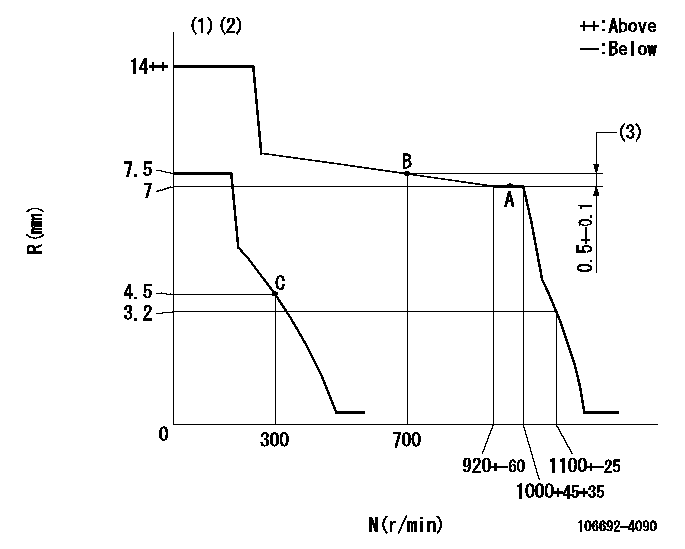
N:Pump speed
R:Rack position (mm)
(1)Target notch: K
(2)The torque control spring must does not have a set force.
(3)Rack difference between N = N1 and N = N2
----------
K=8 N1=1000r/min N2=700r/min
----------
----------
K=8 N1=1000r/min N2=700r/min
----------
Speed control lever angle
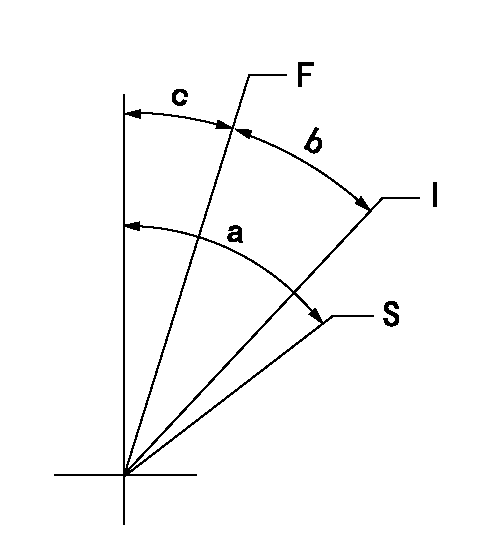
F:Full speed
I:Idle
S:Stop
----------
----------
a=62deg+-3deg b=28deg+-5deg c=21deg+-5deg
----------
----------
a=62deg+-3deg b=28deg+-5deg c=21deg+-5deg
0000001501 LEVER
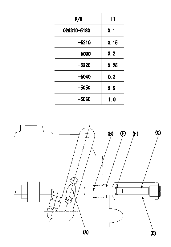
(F) P/N: Part number of the shim
L1:Thickness (mm)
1. Adjustment of the control lever
(1)Perform idling with the control lever (A) contacting the pushrod (B). At this time, confirm that the spring (C) is not compressed by control lever (A)'s operating torque.
(2)To set the stop position, compress spring (C) using the control lever (A) and adjust the rack so that it contacts the guide screw (D) at position L2. Then, set and fix using the lock nut (E). Adjust the rack position L2 at this time using the shim (F).
(3)Confirm that the control lever (A) returns to the idling position when pulled in the stop direction and then released.
----------
L2=0.2~2mm
----------
----------
L2=0.2~2mm
----------
Timing setting

(1)Pump vertical direction
(2)Coupling's key groove position at No 1 cylinder's beginning of injection
(3)-
(4)-
----------
----------
a=(150deg)
----------
----------
a=(150deg)
Information:
Introduction
Do not perform any of the following procedure or order parts until you have read and understand the procedure. The procedure that follows below covers that installation of the new Diesel Exhaust Fluid (DEF) filter.Required Parts
Table 1 below contain the parts needed to complete the installation of the new DEF filter.Note: Only one DEF filter group is required per engine. Use Table 2 to determine which filter is the appropriate filter for each DEF header. Illustration 1 shows the location of the DEF header part number.
Table 1
Item Qty Part Number Part Description
1 1 452-6055 Filter Base As
2 1 453-1604(1) Diesel Exhaust Fluid Filter Gp
3 1 453-1605***#i05999309/d1820e940*** Diesel Exhaust Fluid Filter Gp
4 1 453-1606***#i05999309/d1820e940*** Diesel Exhaust Fluid Filter Gp
5 1 378-3187 Diesel Exhaust Fluid Filter Gp
6 1 423-3251 Connector
7 1 425-0385 Filter As
8 1 391-5262 Gasket
(1) Use Table 2 to choose the correct part that corresponds to the DEF header
Illustration 1 g03745839
(1) Location of DEF header part number
Table 2
DEF Header Part Number Required DEF Filter
434-3241 453-1604
434-3242 453-1605
434-3243 453-1606 Installation Procedure
Illustration 2 g03736523
(1) DEF header
(2) DEF filter
(3) DEF tank
(4) DEF header bolts
Clean the area around DEF header (1). Clear any dirt or debris that could contaminate the DEF tank or lines when removed. Note: If proper cleaning is not performed, DEF pump performance issues or failure may occur.
Disconnect the two DEF lines, two coolant lines, and harness from the DEF header assembly.
Remove the six DEF header screws (4) from the DEF header assembly. Note: Do not discard the screws that secure the DEF header assembly to the DEF tank. The screws will be reused in a later step.
Remove the DEF header assembly. Remove the previous DEF header gasket and discard.
Illustration 3 g03736534
(5) 452-6055 Filter Base As
Install filter base assembly (5) onto the DEF header assembly. Note: Each half of the adapter has two small locking tabs that secure to the bottom side of the DEF header assembly.
Remove the previous 425-0385 Filter As located at the bottom of the DEF pick-up tube.
Install the new 425-0385 Filter As onto the DEF header assembly.
Illustration 4 g03736545
(6) Band clamp
Install the correct DEF filter onto the DEF header adapter and secure using band clamp (6) that is supplied. Torque the band clamp to 4.5 0.7 N m (40 6 lb in).
Install the DEF header assembly back into the DEF tank. Secure the DEF header to the DEF tank using the six screws previously removed in Step 3. Torque the six screws to 5 1 N m (44 9 lb in).
Reconnect the harness, coolant lines, and DEF lines to the DEF header.
Illustration 5 g03736566
(7) DEF pump inlet filter fitting
(8) Main DEF pump filter
Replace DEF pump inlet filter fitting (7) and main DEF pump filter (8). Refer to Disassembly and Assembly, UENR0132, "Diesel Exhaust Fluid Filter - Remove and Install" for the replacement procedure.