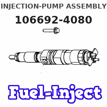
Information injection-pump assembly
ZEXEL
106692-4080
1066924080
KOMATSU
6151711511
6151711511
Rating:
Cross reference number
ZEXEL
106692-4080
1066924080
KOMATSU
6151711511
6151711511
Zexel num
Bosch num
Firm num
Name
Calibration Data:
Adjustment conditions
Test oil
1404 Test oil ISO4113 or {SAEJ967d}
1404 Test oil ISO4113 or {SAEJ967d}
Test oil temperature
degC
40
40
45
Nozzle and nozzle holder
105780-8140
Bosch type code
EF8511/9A
Nozzle
105780-0000
Bosch type code
DN12SD12T
Nozzle holder
105780-2080
Bosch type code
EF8511/9
Opening pressure
MPa
17.2
Opening pressure
kgf/cm2
175
Injection pipe
Outer diameter - inner diameter - length (mm) mm 8-3-600
Outer diameter - inner diameter - length (mm) mm 8-3-600
Overflow valve opening pressure
kPa
157
123
191
Overflow valve opening pressure
kgf/cm2
1.6
1.25
1.95
Tester oil delivery pressure
kPa
157
157
157
Tester oil delivery pressure
kgf/cm2
1.6
1.6
1.6
Direction of rotation (viewed from drive side)
Left L
Left L
Injection timing adjustment
Direction of rotation (viewed from drive side)
Left L
Left L
Injection order
1-5-3-6-
2-4
Pre-stroke
mm
3.75
3.7
3.8
Beginning of injection position
Drive side NO.1
Drive side NO.1
Difference between angles 1
Cal 1-5 deg. 60 59.5 60.5
Cal 1-5 deg. 60 59.5 60.5
Difference between angles 2
Cal 1-3 deg. 120 119.5 120.5
Cal 1-3 deg. 120 119.5 120.5
Difference between angles 3
Cal 1-6 deg. 180 179.5 180.5
Cal 1-6 deg. 180 179.5 180.5
Difference between angles 4
Cyl.1-2 deg. 240 239.5 240.5
Cyl.1-2 deg. 240 239.5 240.5
Difference between angles 5
Cal 1-4 deg. 300 299.5 300.5
Cal 1-4 deg. 300 299.5 300.5
Injection quantity adjustment
Adjusting point
A
Rack position
7
Pump speed
r/min
1000
1000
1000
Average injection quantity
mm3/st.
100.2
98.2
102.2
Max. variation between cylinders
%
0
-3
3
Basic
*
Fixing the lever
*
Injection quantity adjustment_02
Adjusting point
B
Rack position
7.9
Pump speed
r/min
650
650
650
Average injection quantity
mm3/st.
121.8
119.8
123.8
Max. variation between cylinders
%
0
-4
4
Fixing the lever
*
Injection quantity adjustment_03
Adjusting point
C
Rack position
4+-0.5
Pump speed
r/min
325
325
325
Average injection quantity
mm3/st.
12.4
10.9
13.9
Max. variation between cylinders
%
0
-15
15
Fixing the rack
*
Test data Ex:
Governor adjustment
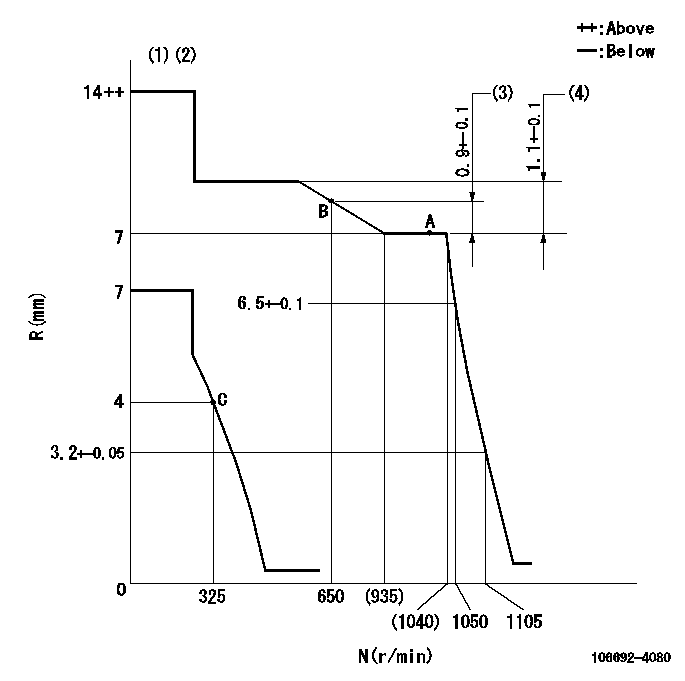
N:Pump speed
R:Rack position (mm)
(1)Target notch: K
(2)Tolerance for racks not indicated: +-0.05mm.
(3)Rack difference between N = N1 and N = N2
(4)Rack difference between N = N3 and N = N4
----------
K=6 N1=1000r/min N2=650r/min N3=1000r/min N4=400r/min
----------
----------
K=6 N1=1000r/min N2=650r/min N3=1000r/min N4=400r/min
----------
Speed control lever angle
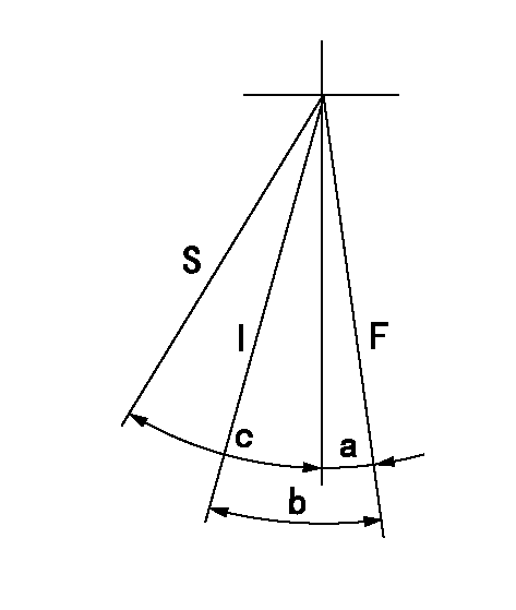
F:Full speed
I:Idle
S:Stop
----------
----------
a=7deg+-5deg b=28deg+-5deg c=32deg+-3deg
----------
----------
a=7deg+-5deg b=28deg+-5deg c=32deg+-3deg
Timing setting

(1)Pump vertical direction
(2)Coupling's key groove position at No 1 cylinder's beginning of injection
(3)-
(4)-
----------
----------
a=(150deg)
----------
----------
a=(150deg)
Information:
Table 1
Required Parts (As determined by application)
Qty Part Number Part Name
1 365-2237 Return Hose Assembly
1 365-2240 Diesel Exhaust Fluid Line As
1 381-0887 Hose As
1 389-2659 Hose As
1 389-9428 Hose As
1 389-9430 Diesel Exhaust Fluid Line As
1 398-9452 Hose As
1 398-9454 Hose As
1 423-3515 Hose As
1 423-5899 Hose As
1 424-0073 Hose As
1 424-1553 Hose As
1 437-9866 Diesel Exhaust Fluid Line As
1 437-9867 Diesel Exhaust Fluid Line As
1 506-5811 Hose As
1 506-5812 Hose As
1 381-0888 Hose As
1 398-9455 Hose As
1 389-2660 Hose As
1 506-5801 Hose As
1 506-5802 Hose As The fault codes are listed in Table 2.
Table 2
J1939 Code and Description CDL Code and Description
4354–5
Aftertreatment 1 Diesel Exhaust Fluid Line
Heater 1 : current Below Normal 3110–5
Aftertreatment #1 SCR Catalyst Reagent Line
Heater #1 : Current Below Normal
4354–6
Aftertreatment 1 Diesel Exhaust Fluid Line
Heater 1 : current Below Normal 3110–6
Aftertreatment #1 SCR Catalyst Reagent Line
Heater #1 : Current Below Normal
4355–5
Aftertreatment 1 Diesel Exhaust Fluid Line
Heater 2 : current Below Normal 3111–5
Aftertreatment #1 SCR Catalyst Reagent Line
Heater #2 : Current Below Normal
4355–6
Aftertreatment 1 Diesel Exhaust Fluid Line
Heater 2: current Below Normal 3111–6
Aftertreatment #1 SCR Catalyst Reagent Line
Heater 2 : Current Below Normal
4356–5
Aftertreatment 1 Diesel Exhaust Fluid Line
Heater 3 : current Below Normal 3112–5
Aftertreatment #1 SCR Catalyst Reagent Line
Heater #3 : Current Below Normal
4356–6
Aftertreatment 1 Diesel Exhaust Fluid Line
Heater 3: current Below Normal 3112–6
Aftertreatment #1 SCR Catalyst Reagent Line
Heater #2 : Current Below Normal