Information injection-pump assembly
BOSCH
9 400 613 072
9400613072
ZEXEL
106691-4110
1066914110

Rating:
Service parts 106691-4110 INJECTION-PUMP ASSEMBLY:
1.
_
7.
COUPLING PLATE
8.
_
9.
_
11.
Nozzle and Holder
12.
Open Pre:MPa(Kqf/cm2)
27.5{280}
15.
NOZZLE SET
Include in #1:
106691-4110
as INJECTION-PUMP ASSEMBLY
Cross reference number
BOSCH
9 400 613 072
9400613072
ZEXEL
106691-4110
1066914110
Zexel num
Bosch num
Firm num
Name
Calibration Data:
Adjustment conditions
Test oil
1404 Test oil ISO4113 or {SAEJ967d}
1404 Test oil ISO4113 or {SAEJ967d}
Test oil temperature
degC
40
40
45
Nozzle and nozzle holder
105780-8140
Bosch type code
EF8511/9A
Nozzle
105780-0000
Bosch type code
DN12SD12T
Nozzle holder
105780-2080
Bosch type code
EF8511/9
Opening pressure
MPa
17.2
Opening pressure
kgf/cm2
175
Injection pipe
Outer diameter - inner diameter - length (mm) mm 8-3-600
Outer diameter - inner diameter - length (mm) mm 8-3-600
Overflow valve
134424-4120
Overflow valve opening pressure
kPa
255
221
289
Overflow valve opening pressure
kgf/cm2
2.6
2.25
2.95
Tester oil delivery pressure
kPa
255
255
255
Tester oil delivery pressure
kgf/cm2
2.6
2.6
2.6
Direction of rotation (viewed from drive side)
Left L
Left L
Injection timing adjustment
Direction of rotation (viewed from drive side)
Left L
Left L
Injection order
1-5-3-6-
2-4
Pre-stroke
mm
3.75
3.7
3.8
Rack position
Point A or more. R=A++
Point A or more. R=A++
Beginning of injection position
Drive side NO.1
Drive side NO.1
Difference between angles 1
Cal 1-5 deg. 60 59.5 60.5
Cal 1-5 deg. 60 59.5 60.5
Difference between angles 2
Cal 1-3 deg. 120 119.5 120.5
Cal 1-3 deg. 120 119.5 120.5
Difference between angles 3
Cal 1-6 deg. 180 179.5 180.5
Cal 1-6 deg. 180 179.5 180.5
Difference between angles 4
Cyl.1-2 deg. 240 239.5 240.5
Cyl.1-2 deg. 240 239.5 240.5
Difference between angles 5
Cal 1-4 deg. 300 299.5 300.5
Cal 1-4 deg. 300 299.5 300.5
Injection quantity adjustment
Adjusting point
A
Rack position
12.9
Pump speed
r/min
1000
1000
1000
Average injection quantity
mm3/st.
140.5
138.5
142.5
Max. variation between cylinders
%
0
-3
3
Basic
*
Fixing the lever
*
Boost pressure
kPa
40
40
Boost pressure
mmHg
300
300
Injection quantity adjustment_02
Adjusting point
C
Rack position
7.5+-0.5
Pump speed
r/min
400
400
400
Average injection quantity
mm3/st.
10
8.5
11.5
Max. variation between cylinders
%
0
-15
15
Fixing the rack
*
Boost pressure
kPa
0
0
0
Boost pressure
mmHg
0
0
0
Injection quantity adjustment_03
Adjusting point
E
Rack position
13.1++
Pump speed
r/min
100
100
100
Average injection quantity
mm3/st.
160
150
170
Fixing the lever
*
Boost pressure
kPa
0
0
0
Boost pressure
mmHg
0
0
0
Rack limit
*
Boost compensator adjustment
Pump speed
r/min
450
450
450
Rack position
R1-1.2
Boost pressure
kPa
8
6.7
9.3
Boost pressure
mmHg
60
50
70
Boost compensator adjustment_02
Pump speed
r/min
450
450
450
Rack position
R1(12.4)
Boost pressure
kPa
26.7
26.7
26.7
Boost pressure
mmHg
200
200
200
Timer adjustment
Pump speed
r/min
800--
Advance angle
deg.
0
0
0
Remarks
Start
Start
Timer adjustment_02
Pump speed
r/min
750
Advance angle
deg.
0.5
Timer adjustment_03
Pump speed
r/min
950
Advance angle
deg.
2
1.7
2.3
Remarks
Finish
Finish
Test data Ex:
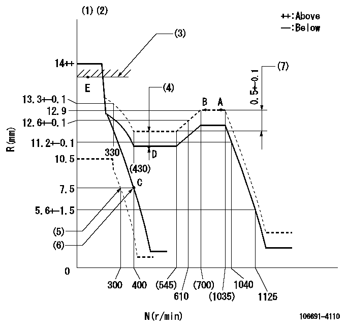
Governor adjustment

N:Pump speed
R:Rack position (mm)
(1)Notch fixed: K
(2)Tolerance for racks not indicated: +-0.05mm.
(3)RACK LIMIT
(4)Boost compensator stroke: BCL
(5)Set idle sub-spring
(6)Main spring setting
(7)Rack difference between N = N1 and N = N2
----------
K=20 BCL=1.2+-0.1mm N1=1000r/min N2=500r/min
----------
----------
K=20 BCL=1.2+-0.1mm N1=1000r/min N2=500r/min
----------
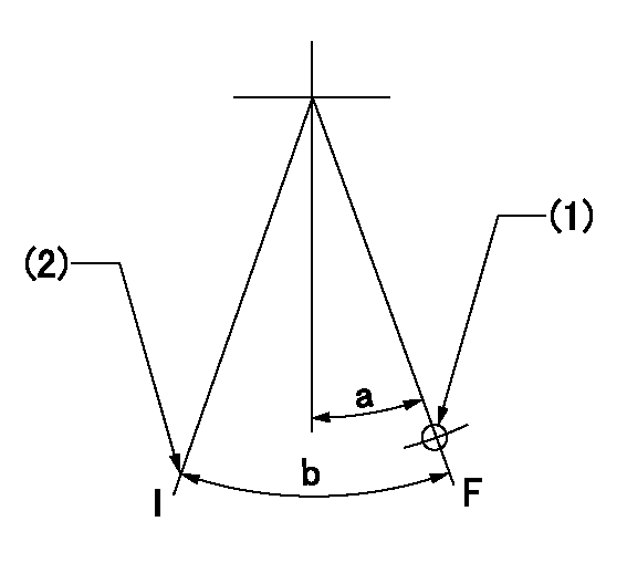
Speed control lever angle

F:Full speed
I:Idle
(1)Use the hole at R = aa
(2)Stopper bolt setting
----------
aa=69mm
----------
a=(10deg)+-5deg b=(26deg)+-5deg
----------
aa=69mm
----------
a=(10deg)+-5deg b=(26deg)+-5deg
Stop lever angle

N:Pump normal
S:Stop the pump.
(1)Rack position = aa, speed = bb (stamp at delivery)
(2)Normal
----------
aa=1-0.5mm bb=0r/min
----------
a=33deg+-5deg b=70deg+-5deg
----------
aa=1-0.5mm bb=0r/min
----------
a=33deg+-5deg b=70deg+-5deg
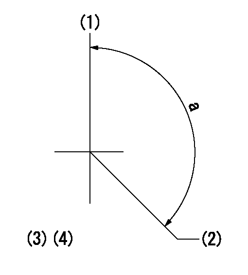
Timing setting

(1)Pump vertical direction
(2)Coupling's key groove position at No 1 cylinder's beginning of injection
(3)B.T.D.C.: aa
(4)-
----------
aa=8deg
----------
a=(140deg)
----------
aa=8deg
----------
a=(140deg)
Information:
Note: Each CCM will support up to a total of eight lists for all GSC's and ECM's. Each list may contain up to eight PID's. The CCM will support up to 64 parameters. However, the total number of PID's able to be broadcast is limited to 48 per controller. Refer to Operation and Maintenance Manual, SEBU6874, "Programming Examples for M5X Protocol".Note: For the older version of CCM, 117-6170 System Communication Module, the total number of PID's able to be broadcast is limited to 31 per module.IID 15 - Status Reply to IID 11, IID 12, and IID 13
This IID is used in order to indicate the validity of a command message that was just sent to the CCM. A typical IID 15 example is: $5001150100cs.
Table 6
IID 15 - Status Reply to IID 11, IID 12, and IID 13
Byte(s) Description
1-4 Standard preamble (50 xxyyzz)
5 IID sent in response to (11, 12, or 82)
6 Status Reply
$00 = IID data is OK
$10 = Invalid list number (greater than 8 or less than 1)
$20 = List is not programmed
$30 = Faulty checksum or command format
7 Checksum of message followed by an ASCII carriage return ($0D) IID 24