Information injection-pump assembly
ZEXEL
106691-3100
1066913100
HINO
220005790A
220005790a

Rating:
Service parts 106691-3100 INJECTION-PUMP ASSEMBLY:
1.
_
7.
COUPLING PLATE
8.
_
9.
_
10.
NOZZLE AND HOLDER ASSY
11.
Nozzle and Holder
12.
Open Pre:MPa(Kqf/cm2)
13.
NOZZLE-HOLDER
14.
NOZZLE
15.
NOZZLE SET
Include in #1:
106691-3100
as INJECTION-PUMP ASSEMBLY
Cross reference number
ZEXEL
106691-3100
1066913100
HINO
220005790A
220005790a
Zexel num
Bosch num
Firm num
Name
106691-3100
220005790A HINO
INJECTION-PUMP ASSEMBLY
ER200 * K
ER200 * K
Calibration Data:
Adjustment conditions
Test oil
1404 Test oil ISO4113 or {SAEJ967d}
1404 Test oil ISO4113 or {SAEJ967d}
Test oil temperature
degC
40
40
45
Nozzle and nozzle holder
105780-8140
Bosch type code
EF8511/9A
Nozzle
105780-0000
Bosch type code
DN12SD12T
Nozzle holder
105780-2080
Bosch type code
EF8511/9
Opening pressure
MPa
17.2
Opening pressure
kgf/cm2
175
Injection pipe
Outer diameter - inner diameter - length (mm) mm 8-3-600
Outer diameter - inner diameter - length (mm) mm 8-3-600
Overflow valve
134424-0920
Overflow valve opening pressure
kPa
162
147
177
Overflow valve opening pressure
kgf/cm2
1.65
1.5
1.8
Tester oil delivery pressure
kPa
157
157
157
Tester oil delivery pressure
kgf/cm2
1.6
1.6
1.6
Direction of rotation (viewed from drive side)
Right R
Right R
Injection timing adjustment
Direction of rotation (viewed from drive side)
Right R
Right R
Injection order
1-4-2-6-
3-5
Pre-stroke
mm
3.45
3.42
3.48
Beginning of injection position
Drive side NO.1
Drive side NO.1
Difference between angles 1
Cal 1-4 deg. 60 59.75 60.25
Cal 1-4 deg. 60 59.75 60.25
Difference between angles 2
Cyl.1-2 deg. 120 119.75 120.25
Cyl.1-2 deg. 120 119.75 120.25
Difference between angles 3
Cal 1-6 deg. 180 179.75 180.25
Cal 1-6 deg. 180 179.75 180.25
Difference between angles 4
Cal 1-3 deg. 240 239.75 240.25
Cal 1-3 deg. 240 239.75 240.25
Difference between angles 5
Cal 1-5 deg. 300 299.75 300.25
Cal 1-5 deg. 300 299.75 300.25
Injection quantity adjustment
Adjusting point
A
Rack position
R1(8.7)
Pump speed
r/min
500
500
500
Average injection quantity
mm3/st.
97
91
103
Max. variation between cylinders
%
0
-4
4
Fixing the lever
*
Injection quantity adjustment_02
Adjusting point
B
Rack position
R1(8.7)
Pump speed
r/min
700
700
700
Average injection quantity
mm3/st.
107
105
109
Max. variation between cylinders
%
0
-2
2
Basic
*
Fixing the lever
*
Injection quantity adjustment_03
Adjusting point
C
Rack position
R1(8.7)
Pump speed
r/min
1150
1150
1150
Average injection quantity
mm3/st.
115
109
121
Max. variation between cylinders
%
0
-4
4
Fixing the lever
*
Injection quantity adjustment_04
Adjusting point
D
Rack position
4.5+-0.5
Pump speed
r/min
225
225
225
Average injection quantity
mm3/st.
11
8
14
Max. variation between cylinders
%
0
-15
15
Fixing the rack
*
Injection quantity adjustment_05
Adjusting point
E
Rack position
8.9+0.2
Pump speed
r/min
330
330
330
Average injection quantity
mm3/st.
97
94
100
Fixing the lever
*
Remarks
Startup boost setting
Startup boost setting
Injection quantity adjustment_06
Adjusting point
F
Rack position
14.4+-0.
5
Pump speed
r/min
100
100
100
Average injection quantity
mm3/st.
187
187
207
Fixing the lever
*
Remarks
After startup boost setting
After startup boost setting
Timer adjustment
Pump speed
r/min
1000--
Advance angle
deg.
0
0
0
Remarks
Start
Start
Timer adjustment_02
Pump speed
r/min
950
Advance angle
deg.
0.3
Timer adjustment_03
Pump speed
r/min
1000
Advance angle
deg.
0.9
Timer adjustment_04
Pump speed
r/min
1050
Advance angle
deg.
1.1
0.6
1.6
Timer adjustment_05
Pump speed
r/min
1150
Advance angle
deg.
2.5
2.2
2.8
Remarks
Finish
Finish
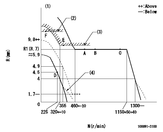
Test data Ex:
Governor adjustment

N:Pump speed
R:Rack position (mm)
(1)After completing adjustment of the broken line, set the lever at the unbroken line position.
(2)Rack limit using stop lever
(3)Excess fuel setting for starting: SXL
(4)Damper spring setting: DL
----------
SXL=8.9+0.2mm DL=2.4-0.2mm
----------
----------
SXL=8.9+0.2mm DL=2.4-0.2mm
----------
0000000901

F:Full load
I:Idle
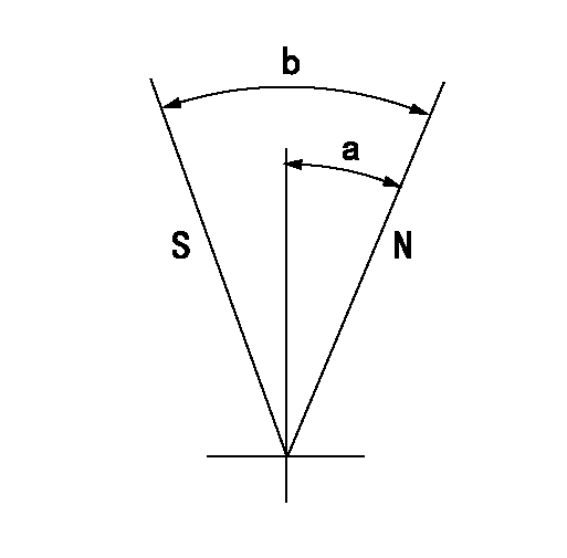
(1)Stopper bolt setting
----------
----------
a=(67deg)+-5deg b=(17deg)+-3deg
----------
----------
a=(67deg)+-5deg b=(17deg)+-3deg
Stop lever angle

N:Pump normal
S:Stop the pump.
----------
----------
a=8deg+-5deg b=40deg+-5deg
----------
----------
a=8deg+-5deg b=40deg+-5deg
0000001501 MICRO SWITCH
Switch adjustment
Adjust the bolt so that the lower lever position is obtained when the switch is turned ON.
(1)Speed N1
(2)Rack position Ra
----------
N1=300+-25r/min Ra=4.5mm
----------
----------
N1=300+-25r/min Ra=4.5mm
----------
Timing setting

(1)Pump vertical direction
(2)Coupling's key groove position at No 1 cylinder's beginning of injection
(3)-
(4)-
----------
----------
a=(40deg)
----------
----------
a=(40deg)
Information:
Highly Recommended
The following equipment is highly recommended:
The Fluke 741B Multimeter is desired. 163-0096 Diagnostic and Calibration Tool
Ladder Viewer Diagnostic Software, YERA0162
The 4C-4029 Adjusting Tool Alternate Recommendations
The Milliampere Loop Simulator and TesterRTD Simulator and Tester Omega CL308Thermocouple Simulator and Tester Omega CL477The Simulator and Tester Omega CL26 for RTD and ThermocoupleThe Fluke 87 9U-7330 Digital Multimeter The Caterpillar Multimeter is also acceptable. 6V-7070 Digital Multimeter The attachments for the Fluke multimeter are in the following list:
Thermocouple Module 80TK is for reading thermocouples.
Immersion Probe 80PK2A can be used with self-sealing adapters.
8T-5200 Signal Generator/Counter is for checking the calibration of the speed switch and for simulating engine speed for the PLC.General Diagnostic Tools For the 3600
Reference: Engine News October 1990"Engine Commissioning and Diagnostic Tooling Kit".The following tools are used for measuring the pressures of the engine. The tools are also use for measuring the temperatures of the engine.
1U-5470 Engine Pressure Group
6V-9130 Temperature Adapter The following list contains the self-sealing adapters that are used for the installation of test ports in piping systems. The sizes of the adapters and the quantities of the adapters depend on the number of test ports that are needed.
5P-2725 Probe Seal Adapter
5P-3591 Probe Adapter
4C-4545 Probe Adapter Group
1U-8865 Infrared Thermometer
139-2788 Crimping Tool A Carrier-Oehler Calibration Pump is used in order to calibrate the setup for the alarms. The pump is also used in order to calibrate the shutdown setup.Contact information for the calibration pump:Carrier-Oehler Company
P.O. Box 40
16965 S. Vincennes
South Holland, Illinois USA 60473
ph: (708) 339-8200, fax: (708) 339-9830
Have questions with 106691-3100?
Group cross 106691-3100 ZEXEL
Hino
106691-3100
220005790A
INJECTION-PUMP ASSEMBLY
ER200
ER200