Information injection-pump assembly
ZEXEL
106691-3050
1066913050
HINO
220003870A
220003870a
Rating:
Cross reference number
ZEXEL
106691-3050
1066913050
HINO
220003870A
220003870a
Zexel num
Bosch num
Firm num
Name
Calibration Data:
Adjustment conditions
Test oil
1404 Test oil ISO4113 or {SAEJ967d}
1404 Test oil ISO4113 or {SAEJ967d}
Test oil temperature
degC
40
40
45
Nozzle and nozzle holder
105780-8140
Bosch type code
EF8511/9A
Nozzle
105780-0000
Bosch type code
DN12SD12T
Nozzle holder
105780-2080
Bosch type code
EF8511/9
Opening pressure
MPa
17.2
Opening pressure
kgf/cm2
175
Injection pipe
Outer diameter - inner diameter - length (mm) mm 8-3-600
Outer diameter - inner diameter - length (mm) mm 8-3-600
Overflow valve opening pressure
kPa
162
147
177
Overflow valve opening pressure
kgf/cm2
1.65
1.5
1.8
Tester oil delivery pressure
kPa
157
157
157
Tester oil delivery pressure
kgf/cm2
1.6
1.6
1.6
Direction of rotation (viewed from drive side)
Right R
Right R
Injection timing adjustment
Direction of rotation (viewed from drive side)
Right R
Right R
Injection order
1-4-2-6-
3-5
Pre-stroke
mm
3.45
3.42
3.48
Beginning of injection position
Drive side NO.1
Drive side NO.1
Difference between angles 1
Cal 1-4 deg. 60 59.75 60.25
Cal 1-4 deg. 60 59.75 60.25
Difference between angles 2
Cyl.1-2 deg. 120 119.75 120.25
Cyl.1-2 deg. 120 119.75 120.25
Difference between angles 3
Cal 1-6 deg. 180 179.75 180.25
Cal 1-6 deg. 180 179.75 180.25
Difference between angles 4
Cal 1-3 deg. 240 239.75 240.25
Cal 1-3 deg. 240 239.75 240.25
Difference between angles 5
Cal 1-5 deg. 300 299.75 300.25
Cal 1-5 deg. 300 299.75 300.25
Injection quantity adjustment
Adjusting point
A
Rack position
8.9
Pump speed
r/min
700
700
700
Average injection quantity
mm3/st.
112
110
114
Max. variation between cylinders
%
0
-2
2
Basic
*
Fixing the lever
*
Injection quantity adjustment_02
Adjusting point
B
Rack position
8.9
Pump speed
r/min
1150
1150
1150
Average injection quantity
mm3/st.
120
117
123
Max. variation between cylinders
%
0
-4
4
Fixing the lever
*
Injection quantity adjustment_03
Adjusting point
C
Rack position
4.5+-0.5
Pump speed
r/min
225
225
225
Average injection quantity
mm3/st.
11
8
14
Max. variation between cylinders
%
0
-15
15
Fixing the rack
*
Timer adjustment
Pump speed
r/min
950
Advance angle
deg.
0.3
Timer adjustment_02
Pump speed
r/min
1000
Advance angle
deg.
0.9
Timer adjustment_03
Pump speed
r/min
1050
Advance angle
deg.
1.1
0.6
1.6
Timer adjustment_04
Pump speed
r/min
1150
Advance angle
deg.
2.5
2.2
2.8
Remarks
Finish
Finish
Test data Ex:
Governor adjustment
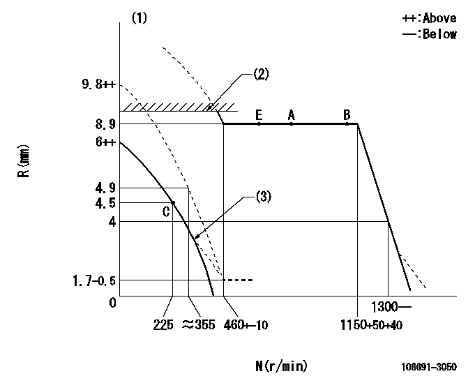
N:Pump speed
R:Rack position (mm)
(1)After completing adjustment of the broken line, set the lever at the unbroken line position.
(2)RACK LIMIT: RAL
(3)Beginning of damper spring operation: DL
----------
RAL=8.9+0.2+0.1mm DL=2.4-0.2mm
----------
----------
RAL=8.9+0.2+0.1mm DL=2.4-0.2mm
----------
0000000901

F:Full load
I:Idle
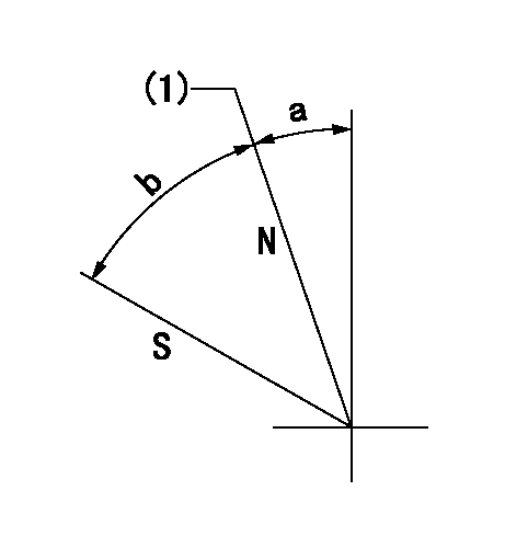
(1)Stopper bolt setting
----------
----------
a=66deg+-5deg b=18deg+-3deg
----------
----------
a=66deg+-5deg b=18deg+-3deg
Stop lever angle
N:Pump normal
S:Stop the pump.
(1)Rack position = aa
----------
aa=9.6+-0.1mm
----------
a=7deg+-5deg b=27deg+-5deg
----------
aa=9.6+-0.1mm
----------
a=7deg+-5deg b=27deg+-5deg
0000001501 MICRO SWITCH
Switch adjustment
Adjust the bolt so that the lower lever position is obtained when the switch is turned ON.
(1)Speed N1
(2)Rack position Ra
----------
N1=300+25r/min Ra=4.5mm
----------
----------
N1=300+25r/min Ra=4.5mm
----------
Information:
Test Procedure
System Operation
The discrete output modules are digital modules. The output modules provide control of voltage. An output module provides power for the following list of functions: Energizing the Lamps, Energizing the Relays, Energizing the Fuel Shutoff Solenoid and Energizing the Air Shutoff Solenoid.
Illustration 1 g00563503
Diagram of the programmable logic controller
Illustration 2 g00563596
Schematic of the discrete outputFunctional Test
Check the electrical connectors and check the wiring.
Bodily contact with electrical potential can cause bodily injury or death.To avoid the possibility of injury or death, ensure that the main power supply has been disconnected before performing any maintenance or removing any modules.
Disconnect the power supply.
Check the electrical connectors and check the wiring for damage or bad connections.
Verify that all modules are properly seated.
Verify the status of the LED on the SLC 5/04.The results of the preceding procedure are in the following list:
All of the components are fully installed. All of the components are free of corrosion. All of the components are free of damage. All of the modules are properly seated. Proceed to 2.
The components are not fully installed. The components are not free of corrosion. The components are damaged. All of the modules are not properly seated. Repair the component. Verify that the repair resolves the problem. STOP.
Test the channel.
Disconnect the load from the channel that is being tested.
Create the condition that activates the channel.The results of the preceding procedure are in the following list:
The LED on the module illuminates. Proceed to 3.
The LED on the module does not illuminate. Replace the module. Verify that the repair resolves the problem. Refer to Maintenance Procedure, "Input Module and Output Module - Replace". Stop.
Measure the voltage of the channel.
Measure the voltage of the channel.The results of the preceding procedure are in the following list:
The voltage of the channel and the voltage of the module are equal. Stop.
The voltage of the channel and the voltage of the module are not equal. Refer to Troubleshooting, "System Power"Stop.