Information injection-pump assembly
BOSCH
9 400 617 783
9400617783
ZEXEL
106691-3042
1066913042
HINO
220201572A
220201572a

Rating:
Cross reference number
BOSCH
9 400 617 783
9400617783
ZEXEL
106691-3042
1066913042
HINO
220201572A
220201572a
Zexel num
Bosch num
Firm num
Name
106691-3042
9 400 617 783
220201572A HINO
INJECTION-PUMP ASSEMBLY
ER100 * K
ER100 * K
Calibration Data:
Adjustment conditions
Test oil
1404 Test oil ISO4113 or {SAEJ967d}
1404 Test oil ISO4113 or {SAEJ967d}
Test oil temperature
degC
40
40
45
Nozzle and nozzle holder
105780-8140
Bosch type code
EF8511/9A
Nozzle
105780-0000
Bosch type code
DN12SD12T
Nozzle holder
105780-2080
Bosch type code
EF8511/9
Opening pressure
MPa
17.2
Opening pressure
kgf/cm2
175
Injection pipe
Outer diameter - inner diameter - length (mm) mm 8-3-600
Outer diameter - inner diameter - length (mm) mm 8-3-600
Overflow valve
134424-0920
Overflow valve opening pressure
kPa
162
147
177
Overflow valve opening pressure
kgf/cm2
1.65
1.5
1.8
Tester oil delivery pressure
kPa
157
157
157
Tester oil delivery pressure
kgf/cm2
1.6
1.6
1.6
Direction of rotation (viewed from drive side)
Right R
Right R
Injection timing adjustment
Direction of rotation (viewed from drive side)
Right R
Right R
Injection order
1-4-2-6-
3-5
Pre-stroke
mm
3.45
3.4
3.5
Beginning of injection position
Drive side NO.1
Drive side NO.1
Difference between angles 1
Cal 1-4 deg. 60 59.5 60.5
Cal 1-4 deg. 60 59.5 60.5
Difference between angles 2
Cyl.1-2 deg. 120 119.5 120.5
Cyl.1-2 deg. 120 119.5 120.5
Difference between angles 3
Cal 1-6 deg. 180 179.5 180.5
Cal 1-6 deg. 180 179.5 180.5
Difference between angles 4
Cal 1-3 deg. 240 239.5 240.5
Cal 1-3 deg. 240 239.5 240.5
Difference between angles 5
Cal 1-5 deg. 300 299.5 300.5
Cal 1-5 deg. 300 299.5 300.5
Injection quantity adjustment
Adjusting point
A
Rack position
10
Pump speed
r/min
700
700
700
Average injection quantity
mm3/st.
95
93
97
Max. variation between cylinders
%
0
-2
2
Basic
*
Fixing the lever
*
Injection quantity adjustment_02
Adjusting point
B
Rack position
6+-0.5
Pump speed
r/min
260
260
260
Average injection quantity
mm3/st.
10.5
7.5
13.5
Max. variation between cylinders
%
0
-15
15
Fixing the rack
*
Timer adjustment
Pump speed
r/min
1000--
Advance angle
deg.
0
0
0
Remarks
Start
Start
Timer adjustment_02
Pump speed
r/min
950
Advance angle
deg.
0.3
Timer adjustment_03
Pump speed
r/min
1000
Advance angle
deg.
0.9
Timer adjustment_04
Pump speed
r/min
-
Advance angle
deg.
2
1.5
2.5
Remarks
Measure the actual speed, stop
Measure the actual speed, stop
Test data Ex:
Governor adjustment
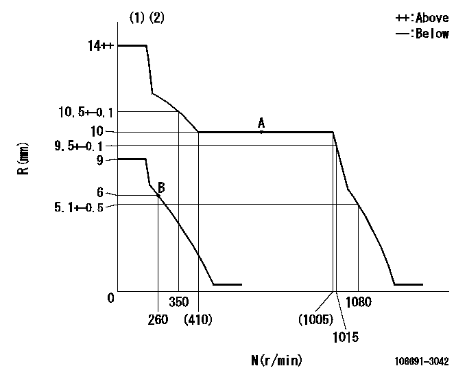
N:Pump speed
R:Rack position (mm)
(1)Target notch: K
(2)Tolerance for racks not indicated: +-0.05mm.
----------
K=10
----------
----------
K=10
----------
Speed control lever angle

F:Full speed
I:Idle
(1)Stopper bolt setting
----------
----------
a=8deg+-5deg b=27deg+-5deg
----------
----------
a=8deg+-5deg b=27deg+-5deg
Stop lever angle
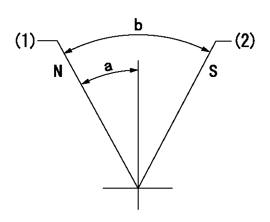
N:Pump normal
S:Stop the pump.
(1)Normal
(2)Rack position aa or less, pump speed bb
----------
aa=5.5mm bb=0r/min
----------
a=27deg+-5deg b=53deg+-5deg
----------
aa=5.5mm bb=0r/min
----------
a=27deg+-5deg b=53deg+-5deg
Timing setting

(1)Pump vertical direction
(2)Coupling's key groove position at No 1 cylinder's beginning of injection
(3)-
(4)-
----------
----------
a=(40deg)
----------
----------
a=(40deg)
Information:
Test Procedure
System Operation
An energized input closes the N.O. contacts. An energized input opens the N.C. contacts. Digital modules are used to determine whether a circuit is ON/OFF. A number of modules are available. The most common modules have sixteen channels.
Illustration 1 g00563503
Diagram of the programmable logic controller
Illustration 2 g00563591
Schematic of the discrete inputFunctional Test
Check the electrical connectors and check the wiring.
Bodily contact with electrical potential can cause bodily injury or death.To avoid the possibility of injury or death, ensure that the main power supply has been disconnected before performing any maintenance or removing any modules.
Disconnect the power supply.
Check the electrical connectors and check the wiring for damage or bad connections.
Verify that all modules are properly seated.
Verify the status of the LED on the SLC 5/04.The results of the preceding procedure are in the following list:
All of the components are fully installed. All of the components are free of corrosion. All of the components are free of damage. All of the modules are properly seated. Proceed to 2.
The components are not fully installed. The components are not free of corrosion. The components are damaged. All of the modules are not properly seated. Repair the component. Verify that the repair resolves the problem. STOP.
Verify the value of the channel.
Get on-line with the PLC.
Locate the software address for the channel.The results of the preceding procedure are in the following list:
The channel has a software address. Proceed to 3.
The channel does not have a software address. Replace the module. Verify that the repair resolves the problem. Refer to Maintenance Procedure, "Input Module and Output Module - Replace". Stop.
Apply the rated voltage.
Apply the rated voltage to the channel.
Verify that the address changed from zero to one.Note: The LED will illuminate when the rated voltage is applied to the channel.The results of the preceding procedure are in the following list:
The software address value changes. The module is functioning normally. Stop.
The software address value does not change. the module is not functioning normally. Replace the module. Verify that the repair resolves the problem. Refer to Maintenance Procedure, "Input Module and Output Module - Replace". Stop.
Have questions with 106691-3042?
Group cross 106691-3042 ZEXEL
Hino
Hino
106691-3042
9 400 617 783
220201572A
INJECTION-PUMP ASSEMBLY
ER100
ER100