Information injection-pump assembly
ZEXEL
106691-3020
1066913020
HINO
220201480A
220201480a

Rating:
Cross reference number
ZEXEL
106691-3020
1066913020
HINO
220201480A
220201480a
Zexel num
Bosch num
Firm num
Name
106691-3020
220201480A HINO
INJECTION-PUMP ASSEMBLY
ER100 * K
ER100 * K
Calibration Data:
Adjustment conditions
Test oil
1404 Test oil ISO4113 or {SAEJ967d}
1404 Test oil ISO4113 or {SAEJ967d}
Test oil temperature
degC
40
40
45
Nozzle and nozzle holder
105780-8140
Bosch type code
EF8511/9A
Nozzle
105780-0000
Bosch type code
DN12SD12T
Nozzle holder
105780-2080
Bosch type code
EF8511/9
Opening pressure
MPa
17.2
Opening pressure
kgf/cm2
175
Injection pipe
Outer diameter - inner diameter - length (mm) mm 8-3-600
Outer diameter - inner diameter - length (mm) mm 8-3-600
Overflow valve
134424-0920
Overflow valve opening pressure
kPa
177
143
211
Overflow valve opening pressure
kgf/cm2
1.8
1.45
2.15
Tester oil delivery pressure
kPa
157
157
157
Tester oil delivery pressure
kgf/cm2
1.6
1.6
1.6
Direction of rotation (viewed from drive side)
Right R
Right R
Injection timing adjustment
Direction of rotation (viewed from drive side)
Right R
Right R
Injection order
1-4-2-6-
3-5
Pre-stroke
mm
3.45
3.4
3.5
Beginning of injection position
Drive side NO.1
Drive side NO.1
Difference between angles 1
Cal 1-4 deg. 60 59.5 60.5
Cal 1-4 deg. 60 59.5 60.5
Difference between angles 2
Cyl.1-2 deg. 120 119.5 120.5
Cyl.1-2 deg. 120 119.5 120.5
Difference between angles 3
Cal 1-6 deg. 180 179.5 180.5
Cal 1-6 deg. 180 179.5 180.5
Difference between angles 4
Cal 1-3 deg. 240 239.5 240.5
Cal 1-3 deg. 240 239.5 240.5
Difference between angles 5
Cal 1-5 deg. 300 299.5 300.5
Cal 1-5 deg. 300 299.5 300.5
Injection quantity adjustment
Adjusting point
A
Rack position
7.8
Pump speed
r/min
900
900
900
Average injection quantity
mm3/st.
97.5
95.5
99.5
Max. variation between cylinders
%
0
-2
2
Basic
*
Fixing the rack
*
Injection quantity adjustment_02
Adjusting point
B
Rack position
3.7+-0.5
Pump speed
r/min
360
360
360
Average injection quantity
mm3/st.
8.2
5.2
11.2
Max. variation between cylinders
%
0
-15
15
Fixing the rack
*
Timer adjustment
Pump speed
r/min
950
Advance angle
deg.
0.3
Timer adjustment_02
Pump speed
r/min
-
Advance angle
deg.
2
2
2
Remarks
Measure the actual speed, stop
Measure the actual speed, stop
Test data Ex:
Governor adjustment
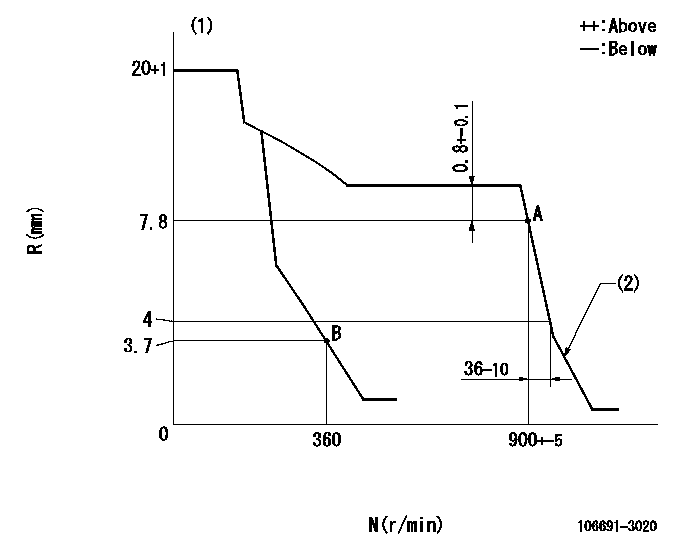
N:Pump speed
R:Rack position (mm)
(1)Target notch: K
(2)Idle sub spring setting: L1.
----------
K=5 L1=4.5+-0.2mm
----------
----------
K=5 L1=4.5+-0.2mm
----------
Speed control lever angle

F:Full speed
I:Idle
----------
----------
a=1deg+-5deg b=22deg+-5deg
----------
----------
a=1deg+-5deg b=22deg+-5deg
Stop lever angle

N:Pump normal
S:Stop the pump.
----------
----------
a=27deg+-5deg b=53deg+-5deg
----------
----------
a=27deg+-5deg b=53deg+-5deg
Information:
Test Procedure
System Operation
The SLC 5/04 diagnostic indicators are located on the front of the following components: Power Supply, CPU and I/O Modules.The diagnostic indicators help trace the source of the fault. Faults can be found in the following components: Input devices, Output devices, Wiring and The controller.The green "DH+" LED is flashing. There are no active nodes on the network.The red "DH+" LED is flashing. There are duplicate active nodes on the link with the same address.The red "FLT" LED is flashing during operation. The processor detects a major fault. The fault is in the processor expansion chassis or the fault is in the memory.
Illustration 1 g00563551
Diagram of the LED indicators
Illustration 2 g00562937
Functional Test
Check the electrical connectors and check the wiring.
Bodily contact with electrical potential can cause bodily injury or death.To avoid the possibility of injury or death, ensure that the main power supply has been disconnected before performing any maintenance or removing any modules.
Disconnect the power supply.
Check the electrical connectors and check the wiring for damage or bad connections.
Verify that all modules are properly seated.
Verify the status of the LED on the SLC 5/04.The results of the preceding procedure are in the following list:
All of the components are fully installed. All of the components are free of corrosion. All of the components are free of damage. All of the modules are properly seated. Proceed to 2.
The components are not fully installed. The components are not free of corrosion. The components are damaged. All of the modules are not properly seated. Repair the component. Verify that the repair resolves the problem. STOP.
Check the communication parameters of the customer supplied devices.
Check the communication parameter of the programmer.The results of the preceding procedure are in the following list:
The programmer address and the processor address are different. Proceed to 3.
The programmer address and the processor address are not different. Set the addresses. Verify that the repair resolves the problem. Stop.
Change the baud rate.
Change the baud rate of the programmer and change the baud rate of the processor.
Increase the maximum node address.Note: The default baud rate is 57,600. The default node address is one.The results of the preceding procedure are in the following list:
No errors are displayed on the LED indicators. Stop.
Errors are displayed on the LED indicators. Proceed to 4.
Check line voltage.
Measure the line voltage at the terminals.
Verify the voltage of the power supply. The power supply voltage should be measured between 21.0 VDC and 28.0 VDC.The results of the preceding procedure are in the following list:
The line voltage is in the range. Replace the processor. Verify that the repair solves the problem. Refer to Maintenance Procedure, "Processor - Replace".
The line voltage is out of the range. Refer to Troubleshooting, "System Power". Stop.
Have questions with 106691-3020?
Group cross 106691-3020 ZEXEL
Hino
106691-3020
220201480A
INJECTION-PUMP ASSEMBLY
ER100
ER100