Information injection-pump assembly
ZEXEL
106691-3010
1066913010
HINO
220002190A
220002190a

Rating:
Cross reference number
ZEXEL
106691-3010
1066913010
HINO
220002190A
220002190a
Zexel num
Bosch num
Firm num
Name
Calibration Data:
Adjustment conditions
Test oil
1404 Test oil ISO4113 or {SAEJ967d}
1404 Test oil ISO4113 or {SAEJ967d}
Test oil temperature
degC
40
40
45
Nozzle and nozzle holder
105780-8140
Bosch type code
EF8511/9A
Nozzle
105780-0000
Bosch type code
DN12SD12T
Nozzle holder
105780-2080
Bosch type code
EF8511/9
Opening pressure
MPa
17.2
Opening pressure
kgf/cm2
175
Injection pipe
Outer diameter - inner diameter - length (mm) mm 8-3-600
Outer diameter - inner diameter - length (mm) mm 8-3-600
Overflow valve
134424-0920
Overflow valve opening pressure
kPa
177
143
211
Overflow valve opening pressure
kgf/cm2
1.8
1.45
2.15
Tester oil delivery pressure
kPa
157
157
157
Tester oil delivery pressure
kgf/cm2
1.6
1.6
1.6
Direction of rotation (viewed from drive side)
Right R
Right R
Injection timing adjustment
Direction of rotation (viewed from drive side)
Right R
Right R
Injection order
1-4-2-6-
3-5
Pre-stroke
mm
3.45
3.42
3.48
Beginning of injection position
Drive side NO.1
Drive side NO.1
Difference between angles 1
Cal 1-4 deg. 60 59.75 60.25
Cal 1-4 deg. 60 59.75 60.25
Difference between angles 2
Cyl.1-2 deg. 120 119.75 120.25
Cyl.1-2 deg. 120 119.75 120.25
Difference between angles 3
Cal 1-6 deg. 180 179.75 180.25
Cal 1-6 deg. 180 179.75 180.25
Difference between angles 4
Cal 1-3 deg. 240 239.75 240.25
Cal 1-3 deg. 240 239.75 240.25
Difference between angles 5
Cal 1-5 deg. 300 299.75 300.25
Cal 1-5 deg. 300 299.75 300.25
Injection quantity adjustment
Adjusting point
A
Rack position
8.9
Pump speed
r/min
500
500
500
Average injection quantity
mm3/st.
102
99
105
Max. variation between cylinders
%
0
-4
4
Fixing the lever
*
Injection quantity adjustment_02
Adjusting point
B
Rack position
8.9
Pump speed
r/min
700
700
700
Average injection quantity
mm3/st.
112
109
115
Max. variation between cylinders
%
0
-2
2
Basic
*
Fixing the lever
*
Injection quantity adjustment_03
Adjusting point
C
Rack position
8.9
Pump speed
r/min
1150
1150
1150
Average injection quantity
mm3/st.
120
117
123
Max. variation between cylinders
%
0
-4
4
Fixing the lever
*
Injection quantity adjustment_04
Adjusting point
D
Rack position
4.5+-0.5
Pump speed
r/min
225
225
225
Average injection quantity
mm3/st.
11
8
14
Max. variation between cylinders
%
0
-15
15
Fixing the rack
*
Injection quantity adjustment_05
Adjusting point
E
Rack position
8.9+0.2
Pump speed
r/min
330
330
330
Average injection quantity
mm3/st.
97
94
100
Fixing the lever
*
Remarks
After startup boost setting
After startup boost setting
Injection quantity adjustment_06
Adjusting point
F
Rack position
14.4+-0.
5
Pump speed
r/min
100
100
100
Average injection quantity
mm3/st.
187
187
207
Fixing the lever
*
Remarks
After startup boost setting
After startup boost setting
Timer adjustment
Pump speed
r/min
1000--
Advance angle
deg.
0
0
0
Remarks
Start
Start
Timer adjustment_02
Pump speed
r/min
950
Advance angle
deg.
0.3
Timer adjustment_03
Pump speed
r/min
1000
Advance angle
deg.
0.9
Timer adjustment_04
Pump speed
r/min
1050
Advance angle
deg.
1.1
0.6
1.6
Timer adjustment_05
Pump speed
r/min
1150
Advance angle
deg.
2.5
2.2
2.8
Remarks
Finish
Finish
Test data Ex:
Governor adjustment
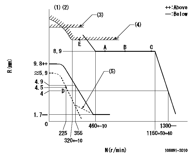
N:Pump speed
R:Rack position (mm)
(1)Beginning of damper spring operation: DL
(2)After adjusting the solid line, set the lever at the dotted line position.
(3)Rack limit using stop lever
(4)Excess fuel setting for starting: SXL
(5)Damper spring setting
----------
DL=2.4-0.2mm SXL=8.9+0.2mm
----------
----------
DL=2.4-0.2mm SXL=8.9+0.2mm
----------
0000000901

F:Full load
I:Idle
(1)Stopper bolt setting
----------
----------
a=66deg+-5deg b=18deg+-3deg
----------
----------
a=66deg+-5deg b=18deg+-3deg
Stop lever angle
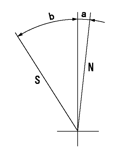
N:Pump normal
S:Stop the pump.
----------
----------
a=8deg+-5deg b=32deg+-5deg
----------
----------
a=8deg+-5deg b=32deg+-5deg
0000001501 MICRO SWITCH
Switch adjustment
Adjust the bolt so that the lower lever position is obtained when the switch is turned ON.
(1)Speed N1
(2)Rack position Ra
----------
N1=300+25r/min Ra=4.5mm
----------
----------
N1=300+25r/min Ra=4.5mm
----------
Information:
Test Procedure
System Operation
The SLC 5/04 diagnostic indicators are located on the front of the following components: Power Supply, CPU and I/O Modules.The diagnostic indicators help trace the source of the fault. Faults can be found in the following components: Input devices, Output devices, Wiring and The controller.The green "RUN" LED is illuminated. The processor is in the "RUN" mode.The red "FLT" LED is flashing during operation. The processor detects a major fault. The fault is in the processor expansion chassis or the fault is in the memory.The amber "FORCE" LED is illuminated. The forces are enabled.The amber "FORCE" LED is not illuminated. No forces are present or no forces are enabled.
Illustration 1 g00563544
Diagram of the LED indicators
Illustration 2 g00562937
Functional Test
Check the electrical connectors and check the wiring.
Bodily contact with electrical potential can cause bodily injury or death.To avoid the possibility of injury or death, ensure that the main power supply has been disconnected before performing any maintenance or removing any modules.
Disconnect the power supply.
Check the electrical connectors and check the wiring for damage or bad connections.
Verify that all modules are properly seated.
Verify the status of the LED on the SLC 5/04.The results of the preceding procedure are in the following list:
All of the components are fully installed. All of the components are free of corrosion. All of the components are free of damage. All of the modules are properly seated. Proceed to 2.
The components are not fully installed. The components are not free of corrosion. The components are damaged. All of the modules are not properly seated. Repair the component. Verify that the repair resolves the problem. STOP.
Clear the fault.
Place the switch in the PROG position.
Place the switch in the RUN position.The results of the preceding procedure are in the following list:
No errors are displayed on the LED indicators. Stop.
Errors are displayed on the LED indicators. Proceed to 3.
Cycle the power.
Secure power to the PLC.
Energize the PLC.The results of the preceding procedure are in the following list:
No errors are displayed on the LED indicators. Stop.
Errors are displayed on the LED indicators. Refer to Maintenance Procedure, "Processor - Replace".