Information injection-pump assembly
ZEXEL
106691-2080
1066912080

Rating:
Cross reference number
ZEXEL
106691-2080
1066912080
Zexel num
Bosch num
Firm num
Name
Calibration Data:
Adjustment conditions
Test oil
1404 Test oil ISO4113 or {SAEJ967d}
1404 Test oil ISO4113 or {SAEJ967d}
Test oil temperature
degC
40
40
45
Nozzle and nozzle holder
105780-8140
Bosch type code
EF8511/9A
Nozzle
105780-0000
Bosch type code
DN12SD12T
Nozzle holder
105780-2080
Bosch type code
EF8511/9
Opening pressure
MPa
17.2
Opening pressure
kgf/cm2
175
Injection pipe
Outer diameter - inner diameter - length (mm) mm 8-3-600
Outer diameter - inner diameter - length (mm) mm 8-3-600
Overflow valve
131424-4620
Overflow valve opening pressure
kPa
255
221
289
Overflow valve opening pressure
kgf/cm2
2.6
2.25
2.95
Tester oil delivery pressure
kPa
157
157
157
Tester oil delivery pressure
kgf/cm2
1.6
1.6
1.6
Direction of rotation (viewed from drive side)
Right R
Right R
Injection timing adjustment
Direction of rotation (viewed from drive side)
Right R
Right R
Injection order
1-5-3-6-
2-4
Pre-stroke
mm
4.8
4.75
4.85
Beginning of injection position
Governor side NO.1
Governor side NO.1
Difference between angles 1
Cal 1-5 deg. 60 59.5 60.5
Cal 1-5 deg. 60 59.5 60.5
Difference between angles 2
Cal 1-3 deg. 120 119.5 120.5
Cal 1-3 deg. 120 119.5 120.5
Difference between angles 3
Cal 1-6 deg. 180 179.5 180.5
Cal 1-6 deg. 180 179.5 180.5
Difference between angles 4
Cyl.1-2 deg. 240 239.5 240.5
Cyl.1-2 deg. 240 239.5 240.5
Difference between angles 5
Cal 1-4 deg. 300 299.5 300.5
Cal 1-4 deg. 300 299.5 300.5
Injection quantity adjustment
Adjusting point
A
Rack position
10.6
Pump speed
r/min
1050
1050
1050
Average injection quantity
mm3/st.
132.3
129.3
135.3
Max. variation between cylinders
%
0
-3
3
Basic
*
Fixing the lever
*
Boost pressure
kPa
49.3
49.3
Boost pressure
mmHg
370
370
Injection quantity adjustment_02
Adjusting point
B
Rack position
4+-0.5
Pump speed
r/min
500
500
500
Average injection quantity
mm3/st.
9.9
8.4
11.4
Max. variation between cylinders
%
0
-15
15
Fixing the rack
*
Boost pressure
kPa
0
0
0
Boost pressure
mmHg
0
0
0
Injection quantity adjustment_03
Adjusting point
C
Rack position
4.9+-0.5
Pump speed
r/min
275
275
275
Average injection quantity
mm3/st.
12.7
10.8
14.6
Fixing the rack
*
Boost pressure
kPa
0
0
0
Boost pressure
mmHg
0
0
0
Remarks
(check)
(check)
Boost compensator adjustment
Pump speed
r/min
500
500
500
Rack position
9.6
Boost pressure
kPa
6.7
5.4
8
Boost pressure
mmHg
50
40
60
Boost compensator adjustment_02
Pump speed
r/min
500
500
500
Rack position
10.6
Boost pressure
kPa
36
29.3
42.7
Boost pressure
mmHg
270
220
320
Timer adjustment
Pump speed
r/min
1050--
Advance angle
deg.
0
0
0
Remarks
Start
Start
Timer adjustment_02
Pump speed
r/min
1000
Advance angle
deg.
0.5
Timer adjustment_03
Pump speed
r/min
1100
Advance angle
deg.
1.5
1
2
Remarks
Finish
Finish
Test data Ex:
Governor adjustment
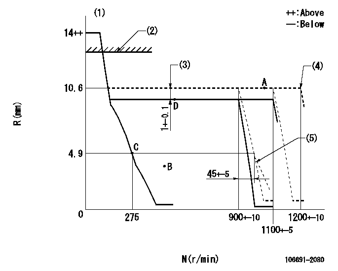
N:Pump speed
R:Rack position (mm)
(1)Target notch: K
(2)RACK LIMIT: RAL
(3)Boost compensator stroke
(4)At shipping
(5)Idle sub spring setting: L1.
----------
K=12 RAL=14+0.2mm L1=4.8+-0.1mm
----------
----------
K=12 RAL=14+0.2mm L1=4.8+-0.1mm
----------
Speed control lever angle
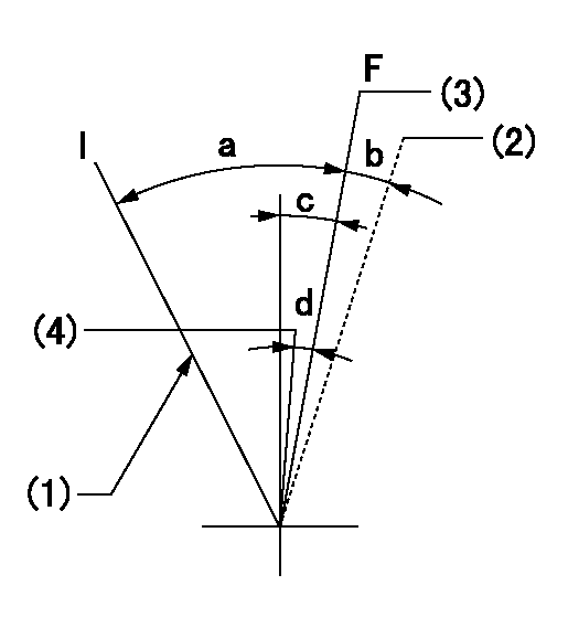
F:Full speed
I:Idle
(1)Stopper bolt setting
(2)At shipping
(3)Pump speed = aa
(4)Pump speed = bb
----------
aa=1100r/min bb=900r/min
----------
a=32deg+-5deg b=(5deg) c=9deg+-5deg d=8deg+-5deg
----------
aa=1100r/min bb=900r/min
----------
a=32deg+-5deg b=(5deg) c=9deg+-5deg d=8deg+-5deg
Stop lever angle
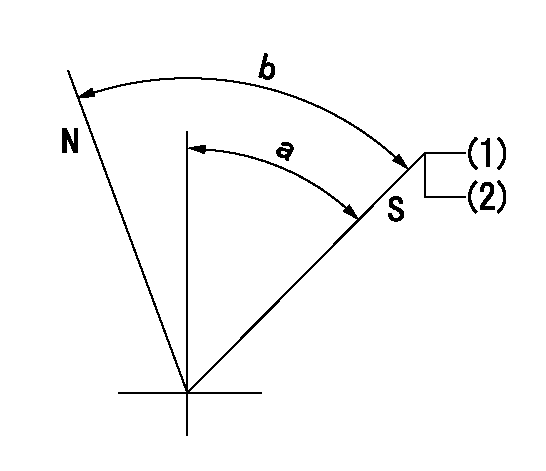
N:Pump normal
S:Stop the pump.
(1)Pump speed aa, rack position bb
(2)Stopper bolt setting
----------
aa=0r/min bb=1-0.2mm
----------
a=50deg+-5deg b=70deg+-5deg
----------
aa=0r/min bb=1-0.2mm
----------
a=50deg+-5deg b=70deg+-5deg
Timing setting

(1)Pump vertical direction
(2)Coupling's key groove position at No 1 cylinder's beginning of injection
(3)-
(4)-
----------
----------
a=(4deg)
----------
----------
a=(4deg)
Information:
The RTD Module Status LED
The module status LED indicators are used in order to indicate operating errors or module errors. You can not recover from the module errors. When an error is present, the RTD module no longer communicates to the processor. The channel states are disabled and the data words are cleared.The RTD Module LED Indicators
Illustration 18 g00563392
The "Module Status" LED is on. The "Channel Status" LED is flashing. Refer to Troubleshooting, "Resistance Temperature Detector".
Illustration 19 g00563417
The "Module Status" LED is off. Cycle the power and refer to Troubleshooting, "Resistance Temperature Detector".Modbus Module
The Modbus module allows an Allen-Bradley SLC 500 to interface with devices that are compatible with Modbus. The module allows a remote access to the MMS.Port Information for the Modbus Module
Illustration 20 g00563418
Information for port 1 is in the following list:
RS-485
1 stop bit and no parity
RTU slave
Baud Rate from the "Setup" Screen
Address from the "Setup" ScreenInformation for port 2 is in the following list:
RS-232
1 stop bit and no parity
RTU slave
Baud Rate from the "Setup" Screen
Address from the "Setup" ScreenJumper Settings for the Modbus Module
Illustration 21 g00563421
Troubleshooting the Modbus Module
Illustration 22 g00563423
Table 1
LED Name Color Status Indication
CFG Green Off The normal state of the LED. No configuration related activity is occurring.