Information injection-pump assembly
ZEXEL
106691-2070
1066912070

Rating:
Cross reference number
ZEXEL
106691-2070
1066912070
Zexel num
Bosch num
Firm num
Name
Calibration Data:
Adjustment conditions
Test oil
1404 Test oil ISO4113 or {SAEJ967d}
1404 Test oil ISO4113 or {SAEJ967d}
Test oil temperature
degC
40
40
45
Nozzle and nozzle holder
105780-8140
Bosch type code
EF8511/9A
Nozzle
105780-0000
Bosch type code
DN12SD12T
Nozzle holder
105780-2080
Bosch type code
EF8511/9
Opening pressure
MPa
17.2
Opening pressure
kgf/cm2
175
Injection pipe
Outer diameter - inner diameter - length (mm) mm 8-3-600
Outer diameter - inner diameter - length (mm) mm 8-3-600
Overflow valve
131424-4620
Overflow valve opening pressure
kPa
255
221
289
Overflow valve opening pressure
kgf/cm2
2.6
2.25
2.95
Tester oil delivery pressure
kPa
157
157
157
Tester oil delivery pressure
kgf/cm2
1.6
1.6
1.6
Direction of rotation (viewed from drive side)
Right R
Right R
Injection timing adjustment
Direction of rotation (viewed from drive side)
Right R
Right R
Injection order
1-5-3-6-
2-4
Pre-stroke
mm
4.8
4.75
4.85
Beginning of injection position
Governor side NO.1
Governor side NO.1
Difference between angles 1
Cal 1-5 deg. 60 59.5 60.5
Cal 1-5 deg. 60 59.5 60.5
Difference between angles 2
Cal 1-3 deg. 120 119.5 120.5
Cal 1-3 deg. 120 119.5 120.5
Difference between angles 3
Cal 1-6 deg. 180 179.5 180.5
Cal 1-6 deg. 180 179.5 180.5
Difference between angles 4
Cyl.1-2 deg. 240 239.5 240.5
Cyl.1-2 deg. 240 239.5 240.5
Difference between angles 5
Cal 1-4 deg. 300 299.5 300.5
Cal 1-4 deg. 300 299.5 300.5
Injection quantity adjustment
Adjusting point
A
Rack position
10.6
Pump speed
r/min
1050
1050
1050
Average injection quantity
mm3/st.
132.3
129.3
135.3
Max. variation between cylinders
%
0
-3
3
Basic
*
Fixing the lever
*
Boost pressure
kPa
49.3
49.3
Boost pressure
mmHg
370
370
Injection quantity adjustment_02
Adjusting point
B
Rack position
4+-0.5
Pump speed
r/min
500
500
500
Average injection quantity
mm3/st.
9.9
8.4
11.4
Max. variation between cylinders
%
0
-15
15
Fixing the rack
*
Boost pressure
kPa
0
0
0
Boost pressure
mmHg
0
0
0
Injection quantity adjustment_03
Adjusting point
C
Rack position
4.9+-0.5
Pump speed
r/min
275
275
275
Average injection quantity
mm3/st.
12.7
10.8
14.6
Fixing the rack
*
Remarks
(check)
(check)
Injection quantity adjustment_04
Adjusting point
D
Rack position
9.6
Pump speed
r/min
500
500
500
Average injection quantity
mm3/st.
116.5
112.5
120.5
Fixing the lever
*
Boost pressure
kPa
0
0
0
Boost pressure
mmHg
0
0
0
Boost compensator adjustment
Pump speed
r/min
500
500
500
Rack position
9.6
Boost pressure
kPa
6.7
5.4
8
Boost pressure
mmHg
50
40
60
Boost compensator adjustment_02
Pump speed
r/min
500
500
500
Rack position
10.6
Boost pressure
kPa
36
29.3
42.7
Boost pressure
mmHg
270
220
320
Timer adjustment
Pump speed
r/min
1050--
Advance angle
deg.
0
0
0
Remarks
Start
Start
Timer adjustment_02
Pump speed
r/min
1000
Advance angle
deg.
0.5
Timer adjustment_03
Pump speed
r/min
1100
Advance angle
deg.
1.5
1
2
Remarks
Finish
Finish
Test data Ex:
Governor adjustment
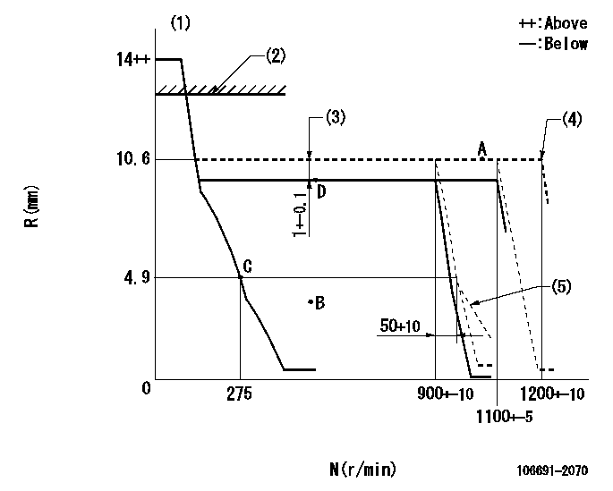
N:Pump speed
R:Rack position (mm)
(1)Target notch: K
(2)RACK LIMIT: RAL
(3)Boost compensator stroke
(4)At shipping
(5)Idle sub spring setting: L1.
----------
K=16 RAL=14+0.2mm L1=4.8+-0.1mm
----------
----------
K=16 RAL=14+0.2mm L1=4.8+-0.1mm
----------
Speed control lever angle
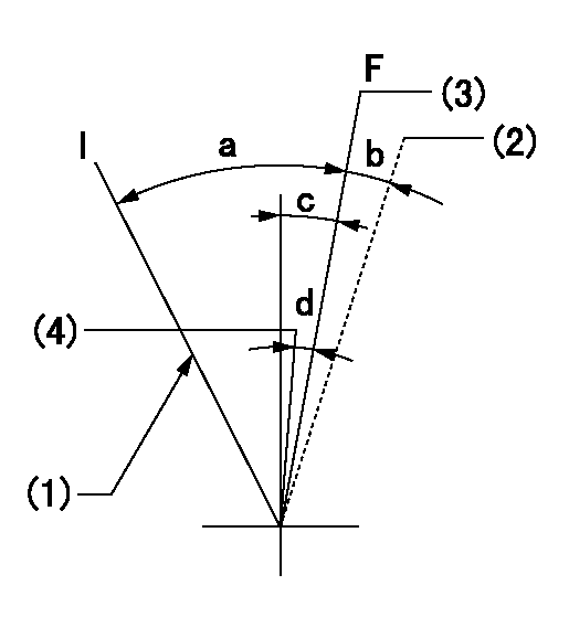
F:Full speed
I:Idle
(1)Stopper bolt setting
(2)At shipping
(3)Pump speed = aa
(4)Pump speed = bb
----------
aa=1100r/min bb=900r/min
----------
a=32deg+-5deg b=(5deg) c=12deg+-5deg d=8deg+-5deg
----------
aa=1100r/min bb=900r/min
----------
a=32deg+-5deg b=(5deg) c=12deg+-5deg d=8deg+-5deg
Stop lever angle
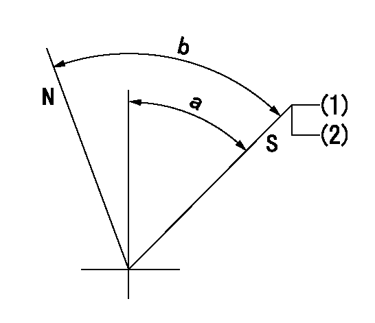
N:Pump normal
S:Stop the pump.
(1)Pump speed aa, rack position bb
(2)Stopper bolt setting
----------
aa=0r/min bb=1-0.2mm
----------
a=50deg+-5deg b=70deg+-5deg
----------
aa=0r/min bb=1-0.2mm
----------
a=50deg+-5deg b=70deg+-5deg
Timing setting

(1)Pump vertical direction
(2)Coupling's key groove position at No 1 cylinder's beginning of injection
(3)-
(4)-
----------
----------
a=(4deg)
----------
----------
a=(4deg)
Information:
Self-Diagnostics
The electronic system has self-diagnostic capabilities. When a problem is detected, a fault indicator is illuminated on the front of the module. A panel of indicators is also located on the MECP.Module Fault Indicators
A fault should be immediately serviced. A fault indicator is illuminated when a problem exists. When the PLC has an active fault, find the appropriate procedure in the troubleshooting section.Operating Information that is Stored in the Programmable Logic Controller
The SLC 5/04 uses a battery in order to provide backup power to the C-MOS RAM.Programmable Logic Controller Chassis or Rack
The PLC chassis contains the following components:
Power Supply
CPU Module
Input Modules
Output Modules
User Defined ModulesThe system uses the Allen-Bradley SLC 500 series of PLC.Central Processing Unit
Illustration 1 g00562937
The SLC 5/04 processor includes a three-position keyswitch on the front panel. The key switches the system from the following three modes of operation: RUN, PROGRAM and REMOTEThe key can be removed in each of the three positions. The mode changes when the position of the key is switched from the RUN position. Do not substitute the keyswitch for a master control relay. Do not substitute the keyswitch for an emergency stop switch.RUN Position
The RUN position places the processor in the run mode. The processor conducts the following functions:
The processor scans the ladder program.
The processor executes the ladder program.
The processor monitors input devices.
The processor energizes the output devices.
The processor acts on the enabled I/O forces.You can only change the processor's mode with the keyswitch. Revising of the program cannot be performed when you are on-line."PROG" Position
The Program position places the processor in the program mode. The processor does not scan the program and the processor does not execute the program. The controller's outputs are de-energized.You can only change the processor's mode with the keyswitch. Revising of the program can be performed when you are on-line.When the keyswitch is in the program position, a qualified technician can use the programmer interface device in order to change the processor's mode.Remote Position
The remote position places the processor in the remote mode. You can only change the processor's mode with the keyswitch. Revising of the program can be performed when you are on-line.When the keyswitch is in the remote position, a qualified technician can use the programmer interface device in order to change the processor's mode.Processor's Fault Indicators
A fault should be immediately serviced. A fault indicator is illuminated when a problem exists. When the PLC has an active fault, find the appropriate procedure in the troubleshooting section.The Processor's Indicators
Six LED indicators are on the front of the CPU module. The indicators show the operating status of your processor. The indicators have the labels that are in the following list:"RUN", "FLT", "BATT", "FORCE", "DH+" and "RS232"Thermocouple Module
The thermocouple module contains diagnostic features that can identify sources of problems. The problems may occur during power up. The problems may occur during normal operation. Each channel can receive a signal from the sensors or from the analog input devices.
Illustration 2 g00562940
LED indicatorsResistance Temperature Detector Module
The RTD module contains diagnostic features that