Information injection-pump assembly
BOSCH
9 400 617 776
9400617776
ZEXEL
106691-2041
1066912041
MITSUBISHI
ME050804
me050804

Rating:
Cross reference number
BOSCH
9 400 617 776
9400617776
ZEXEL
106691-2041
1066912041
MITSUBISHI
ME050804
me050804
Zexel num
Bosch num
Firm num
Name
106691-2041
9 400 617 776
ME050804 MITSUBISHI
INJECTION-PUMP ASSEMBLY
6D22TC * K 14CA INJECTION PUMP ASSY PE6P,6PD PE
6D22TC * K 14CA INJECTION PUMP ASSY PE6P,6PD PE
Calibration Data:
Adjustment conditions
Test oil
1404 Test oil ISO4113 or {SAEJ967d}
1404 Test oil ISO4113 or {SAEJ967d}
Test oil temperature
degC
40
40
45
Nozzle and nozzle holder
105780-8140
Bosch type code
EF8511/9A
Nozzle
105780-0000
Bosch type code
DN12SD12T
Nozzle holder
105780-2080
Bosch type code
EF8511/9
Opening pressure
MPa
17.2
Opening pressure
kgf/cm2
175
Injection pipe
Outer diameter - inner diameter - length (mm) mm 8-3-600
Outer diameter - inner diameter - length (mm) mm 8-3-600
Overflow valve
131424-4620
Overflow valve opening pressure
kPa
255
221
289
Overflow valve opening pressure
kgf/cm2
2.6
2.25
2.95
Tester oil delivery pressure
kPa
157
157
157
Tester oil delivery pressure
kgf/cm2
1.6
1.6
1.6
Direction of rotation (viewed from drive side)
Right R
Right R
Injection timing adjustment
Direction of rotation (viewed from drive side)
Right R
Right R
Injection order
1-5-3-6-
2-4
Pre-stroke
mm
4.8
4.75
4.85
Beginning of injection position
Governor side NO.1
Governor side NO.1
Difference between angles 1
Cal 1-5 deg. 60 59.5 60.5
Cal 1-5 deg. 60 59.5 60.5
Difference between angles 2
Cal 1-3 deg. 120 119.5 120.5
Cal 1-3 deg. 120 119.5 120.5
Difference between angles 3
Cal 1-6 deg. 180 179.5 180.5
Cal 1-6 deg. 180 179.5 180.5
Difference between angles 4
Cyl.1-2 deg. 240 239.5 240.5
Cyl.1-2 deg. 240 239.5 240.5
Difference between angles 5
Cal 1-4 deg. 300 299.5 300.5
Cal 1-4 deg. 300 299.5 300.5
Injection quantity adjustment
Adjusting point
A
Rack position
10.6
Pump speed
r/min
1050
1050
1050
Average injection quantity
mm3/st.
132.3
129.3
135.3
Max. variation between cylinders
%
0
-3
3
Basic
*
Fixing the lever
*
Injection quantity adjustment_02
Adjusting point
B
Rack position
4+-0.5
Pump speed
r/min
500
500
500
Average injection quantity
mm3/st.
9.9
8.4
11.4
Max. variation between cylinders
%
0
-15
15
Fixing the rack
*
Injection quantity adjustment_03
Adjusting point
C
Rack position
4.9+-0.5
Pump speed
r/min
275
275
275
Average injection quantity
mm3/st.
12.7
10.8
14.6
Fixing the rack
*
Remarks
(check)
(check)
Timer adjustment
Pump speed
r/min
1050--
Advance angle
deg.
0
0
0
Remarks
Start
Start
Timer adjustment_02
Pump speed
r/min
1000
Advance angle
deg.
0.5
Timer adjustment_03
Pump speed
r/min
1100
Advance angle
deg.
1.5
1
2
Remarks
Finish
Finish
Test data Ex:
Governor adjustment
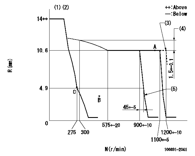
N:Pump speed
R:Rack position (mm)
(1)Target notch: K
(2)Supplied with torque spring not set.
(3)At shipping
(4)Rack difference between N = N1 and N = N2
(5)Idle sub spring setting: L1.
----------
K=12 N1=1100r/min N2=300r/min L1=3.5+-0.1mm
----------
----------
K=12 N1=1100r/min N2=300r/min L1=3.5+-0.1mm
----------
Speed control lever angle
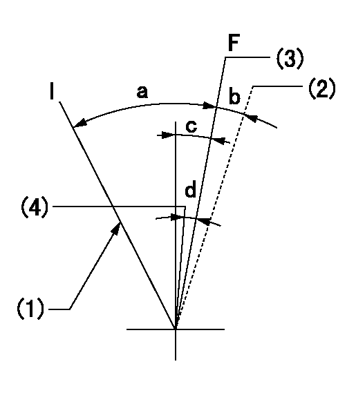
F:Full speed
I:Idle
(1)Stopper bolt setting
(2)At shipping
(3)Set the pump speed at aa
(4)Set the pump speed at bb.
----------
aa=1100r/min bb=900r/min
----------
a=32deg+-5deg b=(5deg) c=9deg+-5deg d=8deg+-5deg
----------
aa=1100r/min bb=900r/min
----------
a=32deg+-5deg b=(5deg) c=9deg+-5deg d=8deg+-5deg
Stop lever angle
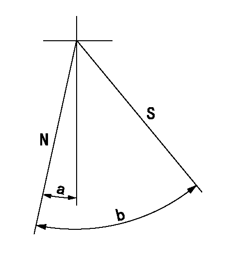
N:Pump normal
S:Stop the pump.
----------
----------
a=19deg+-5deg b=53deg+-5deg
----------
----------
a=19deg+-5deg b=53deg+-5deg
Timing setting

(1)Pump vertical direction
(2)Coupling's key groove position at No 1 cylinder's beginning of injection
(3)-
(4)-
----------
----------
a=(7deg)
----------
----------
a=(7deg)
Information:
Problem 2
The engine does not crank.
Check the engine mounted start switch (EMSS).
Ensure that the emergency stop switch (ES) has been reset.
Place a switch across the terminals of the EMSS.
Close the switch momentarily, but do not start the engine.
Remove the switch when the test is completed. Result
The engine cranks.The EMSS is faulty or the circuit breaker (CB2) must be reset.
The engine does not crank.Go to Step 3.
Check the start/stop switch.
Ensure that the emergency stop switch (ES) has been reset.
Connect a switch with a 2 amp capacity between terminals (TS-21) and (TS-26) of the junction box.
Close the switch momentarily, but do not start the engine.
Disconnect the switch after the test is completed. Results
The engine cranks.The start/stop switch is faulty or the wiring to the switch is faulty. Replace the switch or repair the wiring. The circuit breaker (CB2) may need to be reset.
The engine does not crank.Go to Step 3.
Check the emergency stop switch (ES).
Ensure that the emergency stop switch (ES) has been reset.
Connect a switch with a 2 amp capacity between terminals (TS-26) and (TS-24) of the junction box.
Close the switch momentarily but do not start the engine.
Disconnect the switch after the test is completed. Result
The engine cranks.The emergency stop switch (ES) is faulty.
The engine does not crank.Reset the circuit breaker (CB5) and repeat Step 3. If the engine does not crank go to Step 4.
Check the components of the starting system.
Check the voltage at terminal (TS-24) of the junction box. Result
The voltage is low. Low voltage is between 1 volt and 20 volts.Charge the battery or repair the loose connections between the battery cable terminal and the battery. STOP.
The voltage is above 20 volts.The magnetic switch (MS), the pinion solenoid (PS), or the starting motor (SM) is faulty. The circuit breaker (CB2) may need to be reset. Reset the circuit breaker and repair the component that is faulty.
The voltage is zero (less than 1 volt).The circuit breaker (CB5) is being overloaded or the circuit breaker is faulty. Repair the short circuit or replace the circuit breaker. STOP.Problem 3
The engine starts and shutdown occurs immediately, or engine cranking terminates.
Check the protection switches.
Measure the voltage at terminal (SR2-30) while you crank the engine. Result
The voltage is above 10 volts while you crank the engine. The voltage then decreases to zero when the engine shuts down.The emergency stop switch (ES), the water temperature contactor switch (WTS), and the start/stop switch are opening. Check the start/stop switch first. The switch may be open across the common pair of contacts for the START/RUN switch when the switch is in the START position. The switch may also be open when the switch is released from the START position. Go to Step 7 of "Problem 1".
The voltage is above 10 volts at all times.The diode (D2) is faulty or there is a short across the diode circuit. The engine oil pressure switch (OPS1) may also have an intermittent short in the switch or in the connection. Refer
Have questions with 106691-2041?
Group cross 106691-2041 ZEXEL
Mitsubishi
106691-2041
9 400 617 776
ME050804
INJECTION-PUMP ASSEMBLY
6D22TC
6D22TC