Information injection-pump assembly
ZEXEL
106691-2040
1066912040

Rating:
Cross reference number
ZEXEL
106691-2040
1066912040
Zexel num
Bosch num
Firm num
Name
Calibration Data:
Adjustment conditions
Test oil
1404 Test oil ISO4113 or {SAEJ967d}
1404 Test oil ISO4113 or {SAEJ967d}
Test oil temperature
degC
40
40
45
Nozzle and nozzle holder
105780-8140
Bosch type code
EF8511/9A
Nozzle
105780-0000
Bosch type code
DN12SD12T
Nozzle holder
105780-2080
Bosch type code
EF8511/9
Opening pressure
MPa
17.2
Opening pressure
kgf/cm2
175
Injection pipe
Outer diameter - inner diameter - length (mm) mm 8-3-600
Outer diameter - inner diameter - length (mm) mm 8-3-600
Overflow valve
131424-4620
Overflow valve opening pressure
kPa
255
221
289
Overflow valve opening pressure
kgf/cm2
2.6
2.25
2.95
Tester oil delivery pressure
kPa
157
157
157
Tester oil delivery pressure
kgf/cm2
1.6
1.6
1.6
Direction of rotation (viewed from drive side)
Right R
Right R
Injection timing adjustment
Direction of rotation (viewed from drive side)
Right R
Right R
Injection order
1-5-3-6-
2-4
Pre-stroke
mm
4.8
4.75
4.85
Beginning of injection position
Governor side NO.1
Governor side NO.1
Difference between angles 1
Cal 1-5 deg. 60 59.5 60.5
Cal 1-5 deg. 60 59.5 60.5
Difference between angles 2
Cal 1-3 deg. 120 119.5 120.5
Cal 1-3 deg. 120 119.5 120.5
Difference between angles 3
Cal 1-6 deg. 180 179.5 180.5
Cal 1-6 deg. 180 179.5 180.5
Difference between angles 4
Cyl.1-2 deg. 240 239.5 240.5
Cyl.1-2 deg. 240 239.5 240.5
Difference between angles 5
Cal 1-4 deg. 300 299.5 300.5
Cal 1-4 deg. 300 299.5 300.5
Injection quantity adjustment
Adjusting point
A
Rack position
10.6
Pump speed
r/min
1050
1050
1050
Average injection quantity
mm3/st.
132.3
129.3
135.3
Max. variation between cylinders
%
0
-3
3
Basic
*
Fixing the lever
*
Injection quantity adjustment_02
Adjusting point
B
Rack position
4+-0.5
Pump speed
r/min
500
500
500
Average injection quantity
mm3/st.
9.9
8.4
11.4
Max. variation between cylinders
%
0
-15
15
Fixing the rack
*
Injection quantity adjustment_03
Adjusting point
C
Rack position
4.9+-0.5
Pump speed
r/min
275
275
275
Average injection quantity
mm3/st.
12.7
10.8
14.6
Fixing the rack
*
Remarks
(check)
(check)
Timer adjustment
Pump speed
r/min
1050--
Advance angle
deg.
0
0
0
Remarks
Start
Start
Timer adjustment_02
Pump speed
r/min
1000
Advance angle
deg.
0.5
Timer adjustment_03
Pump speed
r/min
1100
Advance angle
deg.
1.5
1
2
Remarks
Finish
Finish
Test data Ex:
Governor adjustment
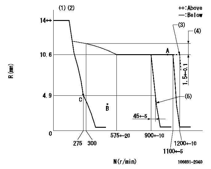
N:Pump speed
R:Rack position (mm)
(1)Target notch: K
(2)Supplied with torque spring not set.
(3)At shipping
(4)Rack difference between N = N1 and N = N2
(5)Idle sub spring setting: L1.
----------
K=12 N1=1100r/min N2=300r/min L1=3.5+-0.1mm
----------
----------
K=12 N1=1100r/min N2=300r/min L1=3.5+-0.1mm
----------
Speed control lever angle
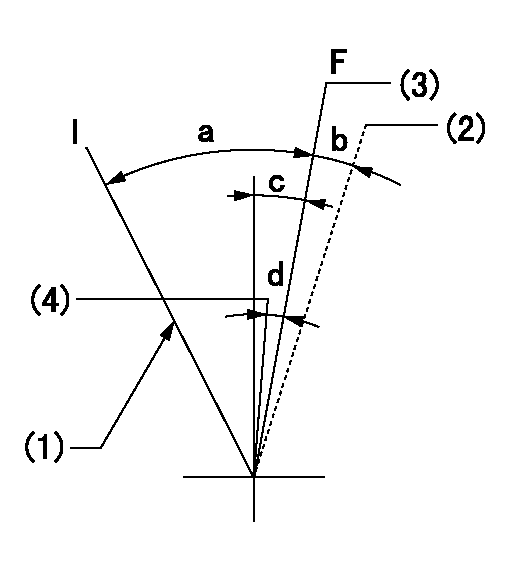
F:Full speed
I:Idle
(1)Stopper bolt setting
(2)At shipping
(3)Set the pump speed at aa
(4)Set the pump speed at bb.
----------
aa=1100r/min bb=900r/min
----------
a=32deg+-5deg b=(5deg) c=9deg+-5deg d=8deg+-5deg
----------
aa=1100r/min bb=900r/min
----------
a=32deg+-5deg b=(5deg) c=9deg+-5deg d=8deg+-5deg
Stop lever angle
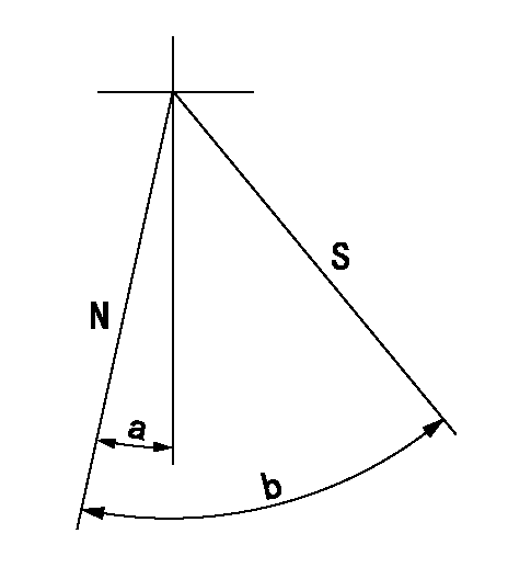
N:Pump normal
S:Stop the pump.
----------
----------
a=19deg+-5deg b=53deg+-5deg
----------
----------
a=19deg+-5deg b=53deg+-5deg
Timing setting

(1)Pump vertical direction
(2)Coupling's key groove position at No 1 cylinder's beginning of injection
(3)-
(4)-
----------
----------
a=(3deg)
----------
----------
a=(3deg)
Information:
Illustration 10 g00562677
Long strings of text will crowd the screen. Keep the custom text as short as possible. If the screen is unreadable shorten the text. Touching the "Done" button returns you to the "Language Conversion" screen. Setup of the Communications
The next two windows are for the setup of communications. The screens are for the two Modbus RTU ports. Port 1 is RS-485 and Port 2 is RS-232C.The "Engine Setup (plc-Baud)" window allows a baud rate to be selected for the two ports. The"Engine Setup (plc-Address)" window is used for setting the external address.Note: Refer to sheet 22 of the MMS System Schematics for cable connections and information.Note: Refer to Systems Operation, "Signal Listing". This is a detailed list of all the Modbus output registers.
Illustration 11 g00594475
Illustration 12 g00594478
Auxiliary Options
Illustration 13 g00594454
Note: If your MMS has been customized at time of sale, some of these options may not be available.The user can configure 4 of the system's input. The terminal blocks for 2 RTDS are located in the MECP. The terminal blocks for 2 4-20mA transducers are also located in the MECP. The spare input may be used for any RTD or 4-20mA analog input.Touch the "Auxiliary Options" picture in order to configure the auxiliary input. Touch the "Auxiliary Options" picture in order to configure the auxiliary outputs. You are now on the "MMS Customation" screen."Edit Gauges" Screen
Touch the "Edit Gauges" button. Four auxiliary analog inputs are available. Each input may be added to the MMS display.Two of the inputs are for RTDS. The RTDS are set within a range of 0 °C (32.0 °F) to 150 °C (302.0 °F). The two remaining inputs are 4-20 mA. The inputs must have ranges that can be configured. This provides appropriate scaling for the numerical display. The ranges also provide appropriate scaling for the graphic display.
Illustration 14 g00594484
Auxiliary Temperature Input Setup
Touch the gauge in order to activate the specific "Auxiliary Temperature Gauge". The green check mark indicates that the gauge is activated.
Illustration 15 g00562687
Setup of the Auxiliary Analog Input
Touch the gauge in order to activate the specific "Auxiliary Analog Gauge". The green check mark indicates that the gauge is selected. Touch the "Gauge Range" box. This will display a numeric keypad. Enter the maximum value for the analog input. Touch the "OK" key. The scaling of the analog input start at zero.Touch the "UUU__XXXXXXXXX" box. This will display a keyboard. Type first 3 characters and then type a space. Type the label for the auxiliary analog input. Touch the "Enter" key in order to proceed.Customize the Auxiliary Labels
Note: The external keyboard will be required for this function.A keyboard with a PS/2 connection may be used. Plug the keyboard into the "keyboard" connection on the back of the PC.You are on the "MMS Customization" screen. Touch the "Edit Auxiliary Labels" button.
Illustration 16 g00594490
Labels for the Auxiliary Alarms
Note: The external keyboard will be required for this function. A keyboard with a PS/2 connection may be used. Plug the keyboard into the "keyboard" connection on the back of the PC.Four