Information injection-pump assembly
BOSCH
9 400 617 774
9400617774
ZEXEL
106691-2001
1066912001
MITSUBISHI
ME059724
me059724

Rating:
Service parts 106691-2001 INJECTION-PUMP ASSEMBLY:
1.
_
7.
COUPLING PLATE
8.
_
9.
_
11.
Nozzle and Holder
12.
Open Pre:MPa(Kqf/cm2)
21.6(220)
15.
NOZZLE SET
Include in #1:
106691-2001
as INJECTION-PUMP ASSEMBLY
Cross reference number
BOSCH
9 400 617 774
9400617774
ZEXEL
106691-2001
1066912001
MITSUBISHI
ME059724
me059724
Zexel num
Bosch num
Firm num
Name
Calibration Data:
Adjustment conditions
Test oil
1404 Test oil ISO4113 or {SAEJ967d}
1404 Test oil ISO4113 or {SAEJ967d}
Test oil temperature
degC
40
40
45
Nozzle and nozzle holder
105780-8140
Bosch type code
EF8511/9A
Nozzle
105780-0000
Bosch type code
DN12SD12T
Nozzle holder
105780-2080
Bosch type code
EF8511/9
Opening pressure
MPa
17.2
Opening pressure
kgf/cm2
175
Injection pipe
Outer diameter - inner diameter - length (mm) mm 8-3-600
Outer diameter - inner diameter - length (mm) mm 8-3-600
Overflow valve
131424-4620
Overflow valve opening pressure
kPa
255
221
289
Overflow valve opening pressure
kgf/cm2
2.6
2.25
2.95
Tester oil delivery pressure
kPa
157
157
157
Tester oil delivery pressure
kgf/cm2
1.6
1.6
1.6
Direction of rotation (viewed from drive side)
Right R
Right R
Injection timing adjustment
Direction of rotation (viewed from drive side)
Right R
Right R
Injection order
1-5-3-6-
2-4
Pre-stroke
mm
4.8
4.75
4.85
Beginning of injection position
Governor side NO.1
Governor side NO.1
Difference between angles 1
Cal 1-5 deg. 60 59.5 60.5
Cal 1-5 deg. 60 59.5 60.5
Difference between angles 2
Cal 1-3 deg. 120 119.5 120.5
Cal 1-3 deg. 120 119.5 120.5
Difference between angles 3
Cal 1-6 deg. 180 179.5 180.5
Cal 1-6 deg. 180 179.5 180.5
Difference between angles 4
Cyl.1-2 deg. 240 239.5 240.5
Cyl.1-2 deg. 240 239.5 240.5
Difference between angles 5
Cal 1-4 deg. 300 299.5 300.5
Cal 1-4 deg. 300 299.5 300.5
Injection quantity adjustment
Adjusting point
A
Rack position
11.9
Pump speed
r/min
750
750
750
Average injection quantity
mm3/st.
157.5
154.5
160.5
Max. variation between cylinders
%
0
-3
3
Basic
*
Fixing the lever
*
Injection quantity adjustment_02
Adjusting point
C
Rack position
4+-0.5
Pump speed
r/min
500
500
500
Average injection quantity
mm3/st.
9.9
8.4
11.4
Max. variation between cylinders
%
0
-15
15
Fixing the rack
*
Injection quantity adjustment_03
Adjusting point
B
Rack position
4.9+-0.5
Pump speed
r/min
300
300
300
Average injection quantity
mm3/st.
12.7
10.8
14.6
Fixing the rack
*
Remarks
(check)
(check)
Timer adjustment
Pump speed
r/min
1050--
Advance angle
deg.
0
0
0
Remarks
Start
Start
Timer adjustment_02
Pump speed
r/min
1000
Advance angle
deg.
0.5
Timer adjustment_03
Pump speed
r/min
1100
Advance angle
deg.
1.5
1
2
Remarks
Finish
Finish
Test data Ex:
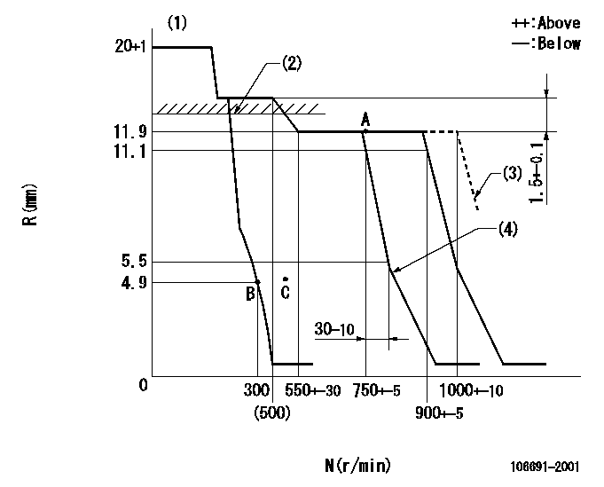
Governor adjustment

N:Pump speed
R:Rack position (mm)
(1)Target notch: K
(2)RACK LIMIT: RAL
(3)At shipping
(4)Idle sub spring setting: L1.
----------
K=12 RAL=12.2+0.2mm L1=4.6+-0.1mm
----------
----------
K=12 RAL=12.2+0.2mm L1=4.6+-0.1mm
----------
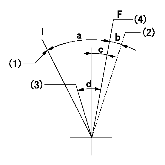
Speed control lever angle

F:Full speed
I:Idle
(1)Stopper bolt setting
(2)At shipping
(3)Pump speed = aa
(4)Pump speed = bb
----------
aa=750r/min bb=900r/min
----------
a=26deg+-5deg b=(5deg) c=2deg+-5deg d=6deg+-5deg
----------
aa=750r/min bb=900r/min
----------
a=26deg+-5deg b=(5deg) c=2deg+-5deg d=6deg+-5deg
Stop lever angle

N:Pump normal
S:Stop the pump.
----------
----------
a=19deg+-5deg b=53deg+-5deg
----------
----------
a=19deg+-5deg b=53deg+-5deg
Timing setting

(1)Pump vertical direction
(2)Coupling's key groove position at No 1 cylinder's beginning of injection
(3)-
(4)-
----------
----------
a=(7deg)
----------
----------
a=(7deg)
Information:
Depending on application severity and localized environmental conditions, and also depending on maintenance practices, operating Direct Injection (DI) diesel engines and operating PC (Precombustion Chamber) diesel engines on fuel with sulfur levels over 0.1 percent (1000 ppm) may require significantly shortened oil change intervals in order to help maintain adequate wear protection. Refer to this Special Publication, "Fuel Specifications" section, “Diesel Fuel Sulfur” topic for additional information.
Note: Do NOT use only this Special Publication as a basis for determining oil drain intervals.This Special Publication does not address recommended oil drain intervals, but rather provides guidance that should be used with your specific engine/machine Operation and Maintenance Manuals in determining acceptable oil drain intervals. Consult your engine/machine Operation and Maintenance Manuals, and consult your Cat dealer for additional guidance, including but not limited to guidance on establishing optimized and/or acceptable oil drain intervals.Total Base Number (TBN) and Fuel Sulfur Levels for Engines That Use Heavy Fuel Oil (HFO)
Note: Only specially configured 3600 diesel engines can use HFO.The use of Cat S O S Services oil analysis is recommended for determining oil life.TBN is also commonly referred to as Base Number (BN).Generally, lubrication oils for engines that use heavy fuel oil are available with a TBN in a range of 20 to 50 ("ASTM D2896"). Oil companies list these oils that have a high TBN as oils for “trunk piston” or “medium speed marine” diesel engines. Most of the Caterpillar experience is with the oils that have a TBN of 30 or 40. The TBN for a new oil depends on the fuel sulfur level. The TBN for a new oil depends on the fuel sulfur level. For 3600 Series engines that use heavy fuel oil, the minimum new oil TBN must be 20 as determined by the "ASTM D2896" procedure.Engine oils of high TBN can neutralize the sulfur in the fuel and allow for long drain interval. However, oils with a high TBN and/or high ash can produce excessive deposits on the pistons and valves. These deposits can lead to the following results:
A loss of stable oil control
Polishing of the cylinder bore
Guttering of the valvesHigh quality engine oils that are formulated for operation using HFO are balanced to allow the desired oil drain intervals while protecting engines from excessive deposits. The oil must also have the proof of performance that is explained in the Selecting a Commercial Oil article.Use the following guidelines for fuel sulfur levels that exceed 2.0 percent:
Choose an oil with the highest TBN that meets the Caterpillar performance requirements.
Base the oil change interval on the oil analysis. Ensure that the oil analysis includes the condition of the oil, TBN, and a wear metal analysis. Reduce the oil change interval, if necessary.TBN testing is an optional part of the S O S Services oil analysis program. TBN testing may be done in addition to the standard S O S Services tests for oil deterioration. In most applications, the S O S Services tests for oxidation, sulfation, viscosity,