Information injection-pump assembly
BOSCH
9 400 617 773
9400617773
ZEXEL
106691-1971
1066911971
ISUZU
1156007350
1156007350

Rating:
Cross reference number
BOSCH
9 400 617 773
9400617773
ZEXEL
106691-1971
1066911971
ISUZU
1156007350
1156007350
Zexel num
Bosch num
Firm num
Name
106691-1971
9 400 617 773
1156007350 ISUZU
INJECTION-PUMP ASSEMBLY
E120 * K 14CA INJECTION PUMP ASSY PE6P,6PD PE
E120 * K 14CA INJECTION PUMP ASSY PE6P,6PD PE
Calibration Data:
Adjustment conditions
Test oil
1404 Test oil ISO4113 or {SAEJ967d}
1404 Test oil ISO4113 or {SAEJ967d}
Test oil temperature
degC
40
40
45
Nozzle and nozzle holder
105780-8140
Bosch type code
EF8511/9A
Nozzle
105780-0000
Bosch type code
DN12SD12T
Nozzle holder
105780-2080
Bosch type code
EF8511/9
Opening pressure
MPa
17.2
Opening pressure
kgf/cm2
175
Injection pipe
Outer diameter - inner diameter - length (mm) mm 8-3-600
Outer diameter - inner diameter - length (mm) mm 8-3-600
Overflow valve
132424-0620
Overflow valve opening pressure
kPa
157
123
191
Overflow valve opening pressure
kgf/cm2
1.6
1.25
1.95
Tester oil delivery pressure
kPa
157
157
157
Tester oil delivery pressure
kgf/cm2
1.6
1.6
1.6
Direction of rotation (viewed from drive side)
Right R
Right R
Injection timing adjustment
Direction of rotation (viewed from drive side)
Right R
Right R
Injection order
1-4-2-6-
3-5
Pre-stroke
mm
3
2.95
3.05
Beginning of injection position
Drive side NO.1
Drive side NO.1
Difference between angles 1
Cal 1-4 deg. 60 59.5 60.5
Cal 1-4 deg. 60 59.5 60.5
Difference between angles 2
Cyl.1-2 deg. 120 119.5 120.5
Cyl.1-2 deg. 120 119.5 120.5
Difference between angles 3
Cal 1-6 deg. 180 179.5 180.5
Cal 1-6 deg. 180 179.5 180.5
Difference between angles 4
Cal 1-3 deg. 240 239.5 240.5
Cal 1-3 deg. 240 239.5 240.5
Difference between angles 5
Cal 1-5 deg. 300 299.5 300.5
Cal 1-5 deg. 300 299.5 300.5
Injection quantity adjustment
Adjusting point
A
Rack position
7.6
Pump speed
r/min
1000
1000
1000
Average injection quantity
mm3/st.
112.9
109.1
116.7
Max. variation between cylinders
%
0
-3
3
Fixing the lever
*
Injection quantity adjustment_02
Adjusting point
B
Rack position
7.6
Pump speed
r/min
700
700
700
Average injection quantity
mm3/st.
110.2
106.4
114
Max. variation between cylinders
%
0
-3
3
Basic
*
Fixing the lever
*
Injection quantity adjustment_03
Adjusting point
C
Rack position
8.1
Pump speed
r/min
420
420
420
Average injection quantity
mm3/st.
102.8
98.8
106.8
Max. variation between cylinders
%
0
-4
4
Fixing the lever
*
Injection quantity adjustment_04
Adjusting point
D
Rack position
5.5+-0.5
Pump speed
r/min
225
225
225
Average injection quantity
mm3/st.
22.5
19.3
25.7
Max. variation between cylinders
%
0
-13
13
Fixing the rack
*
Test data Ex:
Governor adjustment

N:Pump speed
R:Rack position (mm)
(1)Target notch: K
(2)Set so that the point C's injection quantity is obtained. Is not effective when C's rack position R = R1.
----------
K=10 R1=7.5mm
----------
----------
K=10 R1=7.5mm
----------
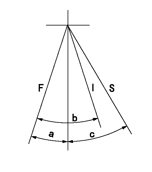
Speed control lever angle

F:Full speed
I:Idle
S:Stop
----------
----------
a=8deg+-5deg b=23deg+-5deg c=32deg+-3deg
----------
----------
a=8deg+-5deg b=23deg+-5deg c=32deg+-3deg
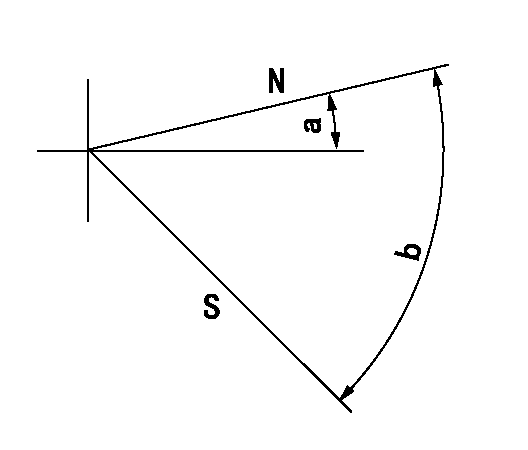
Stop lever angle

N:Pump normal
S:Stop the pump.
----------
----------
a=(10deg) b=(53deg)
----------
----------
a=(10deg) b=(53deg)
Information:
Illustration 1 g00562591
Marine Engine Control Panel
The Marine Engine Control Panel contains the following components:
A personal computer (PC) that displays the operating information
A minimum protection backup relay system
Control switches for starting the engine
Control switches for stopping the engine
The engine speed switch
A Programmable Logic ControllerPersonal Computer
The PC display provides the engine status for the operator.Control Switches
The following controls are located on the Marine Engine Control Panel:
"EMERGENCY STOP" button
"OFF/RESET-LOCAL-REMOTE" switch
"PRELUBE-RUN-START" switch
"FUEL CONTROL" switch
"HORN SILENCE-LAMP TEST" switchThe control switch on the Marine Engine Control Panel permits local control of the engine or remote control of the engine. This switch can also be placed in the OFF/RESET position. The "FUEL CONTROL" switch can be placed in the OFF position or the ON position.Weight of the Marine Monitoring System
Each of the following part numbers have a combined weight of 90 kg (198 lb):
146-5522 EMCP Electronic Control
146-5523 EMCP Electronic Control
146-5524 EMCP Electronic Control
146-5525 EMCP Electronic Control The 147-5676 Instrument Panel Mounting has a weight of 86 kg (190 lb).Programmable Logic Controller
The programmable logic controller provides complete monitoring and control for a Caterpillar 3600 Engine. The basic modular programmable logic controller consists of the following components:
Power Supply
Central Processing Unit Module (CPU)
Chassis
Input Modules
Output Modules
Engine Speed SwitchThe programmable logic controller is the computer that conducts the following engine functions:
Control
Monitor
ProtectionThe CPU in the programmable logic controller contains the software that controls programmable logic controller behavior.The following components are used as engine sensors: contactors, thermocouples, resistance temperature detectors (RTDS) and transducers.Power Supply
The power supply delivers 24 VDC for the following components: the CPU, the chassis, the control panel, the input modules and the output modules. The 24 VDC is typically provided by a battery set.Central Processing Unit Module
The operator can configure the memory. The operator can configure the memory for data. The operator can also configure the memory for the storage of programs. The memory size is adjustable from 1K to 64K. The CPU is supported by a variety of modules. These modules include digital modules, analog modules, and smart modules. The CPU is seated in slot 0 of the programmable logic controller chassis.Discrete Input Modules
The discrete input modules are in the following list:
Thermocouple Module
RTD Input Module
Digital Modules
Analog ModulesWhen you apply a voltage to the channel, the relay is energized. An energized input closes all of the contacts that are normally open. An energized input will open all of the contacts that are normally closed. Digital modules are used to determine whether a circuit is ON/OFF. A number of modules are available. The MMS modules have sixteen channels.Discrete Output Modules
The programmable logic controller discrete output modules consist of analog modules and digital modules. Voltage control is provided by the output modules. A module provides power for the following list of functions: energizing the lamps, energizing the relays, energizing the fuel shutoff solenoid and energizing the air shutoff solenoid.Engine Speed Switch
The speed switch accepts a signal from the magnetic pickup. The magnetic pickup is mounted on the engine. The speed switch determines the engine speed from the signal. The speed switch provides
Have questions with 106691-1971?
Group cross 106691-1971 ZEXEL
Isuzu
106691-1971
9 400 617 773
1156007350
INJECTION-PUMP ASSEMBLY
E120
E120