Information injection-pump assembly
ZEXEL
106691-0550
1066910550

Rating:
Service parts 106691-0550 INJECTION-PUMP ASSEMBLY:
1.
_
7.
COUPLING PLATE
8.
_
9.
_
11.
Nozzle and Holder
16600-96578
12.
Open Pre:MPa(Kqf/cm2)
19.6{200}
15.
NOZZLE SET
Include in #1:
106691-0550
as INJECTION-PUMP ASSEMBLY
Cross reference number
ZEXEL
106691-0550
1066910550
Zexel num
Bosch num
Firm num
Name
106691-0550
INJECTION-PUMP ASSEMBLY
Calibration Data:
Adjustment conditions
Test oil
1404 Test oil ISO4113 or {SAEJ967d}
1404 Test oil ISO4113 or {SAEJ967d}
Test oil temperature
degC
40
40
45
Nozzle and nozzle holder
105780-8140
Bosch type code
EF8511/9A
Nozzle
105780-0000
Bosch type code
DN12SD12T
Nozzle holder
105780-2080
Bosch type code
EF8511/9
Opening pressure
MPa
17.2
Opening pressure
kgf/cm2
175
Injection pipe
Outer diameter - inner diameter - length (mm) mm 8-3-600
Outer diameter - inner diameter - length (mm) mm 8-3-600
Overflow valve
132424-0620
Overflow valve opening pressure
kPa
157
123
191
Overflow valve opening pressure
kgf/cm2
1.6
1.25
1.95
Tester oil delivery pressure
kPa
157
157
157
Tester oil delivery pressure
kgf/cm2
1.6
1.6
1.6
Direction of rotation (viewed from drive side)
Right R
Right R
Injection timing adjustment
Direction of rotation (viewed from drive side)
Right R
Right R
Injection order
1-4-2-6-
3-5
Pre-stroke
mm
3.65
3.6
3.7
Beginning of injection position
Drive side NO.1
Drive side NO.1
Difference between angles 1
Cal 1-4 deg. 60 59.5 60.5
Cal 1-4 deg. 60 59.5 60.5
Difference between angles 2
Cyl.1-2 deg. 120 119.5 120.5
Cyl.1-2 deg. 120 119.5 120.5
Difference between angles 3
Cal 1-6 deg. 180 179.5 180.5
Cal 1-6 deg. 180 179.5 180.5
Difference between angles 4
Cal 1-3 deg. 240 239.5 240.5
Cal 1-3 deg. 240 239.5 240.5
Difference between angles 5
Cal 1-5 deg. 300 299.5 300.5
Cal 1-5 deg. 300 299.5 300.5
Injection quantity adjustment
Adjusting point
A
Rack position
8
Pump speed
r/min
650
650
650
Average injection quantity
mm3/st.
114.5
112.5
116.5
Max. variation between cylinders
%
0
-4
4
Basic
*
Fixing the lever
*
Remarks
Startup boost setting
Startup boost setting
Injection quantity adjustment_02
Adjusting point
C
Rack position
5.1+-0.5
Pump speed
r/min
260
260
260
Average injection quantity
mm3/st.
12.5
11.2
13.8
Max. variation between cylinders
%
0
-10
10
Fixing the rack
*
Timer adjustment
Pump speed
r/min
900--
Advance angle
deg.
0
0
0
Remarks
Start
Start
Timer adjustment_02
Pump speed
r/min
850
Advance angle
deg.
0.5
Timer adjustment_03
Pump speed
r/min
1050
Advance angle
deg.
3.5
3
4
Remarks
Finish
Finish
Test data Ex:
Governor adjustment
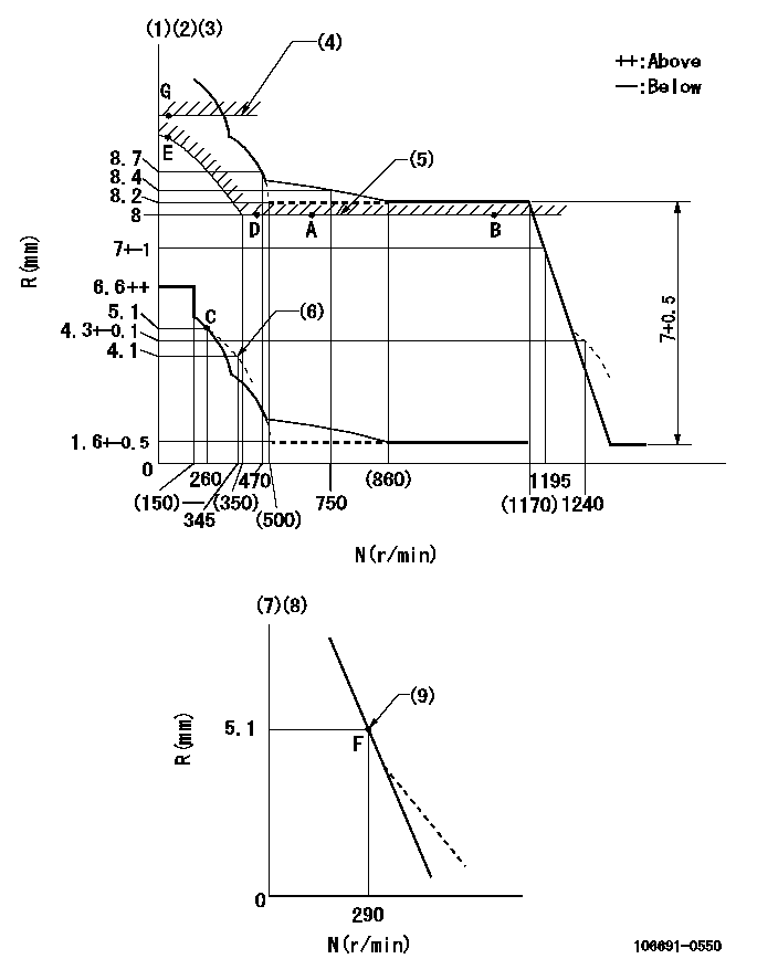
N:Pump speed
R:Rack position (mm)
(1)Lever ratio: RT
(2)Target shim dimension: TH
(3)Tolerance for racks not indicated: +-0.05mm.
(4)Rack limit using the stop lever: R1
(5)Excess fuel setting for starting
(6)Damper spring setting
(7)Variable speed specification: idling adjustment
(8)Fix the lever at the full-load position at delivery.
(9)Main spring setting
----------
RT=1 TH=2.8mm R1=(11)+-0.1mm
----------
----------
RT=1 TH=2.8mm R1=(11)+-0.1mm
----------
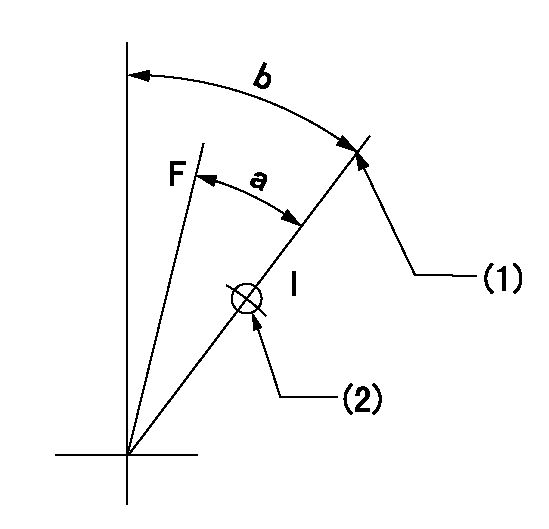
Speed control lever angle

F:Full speed
I:Idle
(1)Pump speed = aa
(2)Set the stopper bolt (fixed at full-load position at delivery.)
----------
aa=290r/min
----------
a=13.5deg+-5deg b=3.5deg+-5deg
----------
aa=290r/min
----------
a=13.5deg+-5deg b=3.5deg+-5deg
0000000901
F:Full load
I:Idle
(1)Stopper bolt setting
(2)Use the hole at R = aa
----------
aa=51mm
----------
a=24.5deg+-3deg b=45deg+-5deg
----------
aa=51mm
----------
a=24.5deg+-3deg b=45deg+-5deg
Stop lever angle
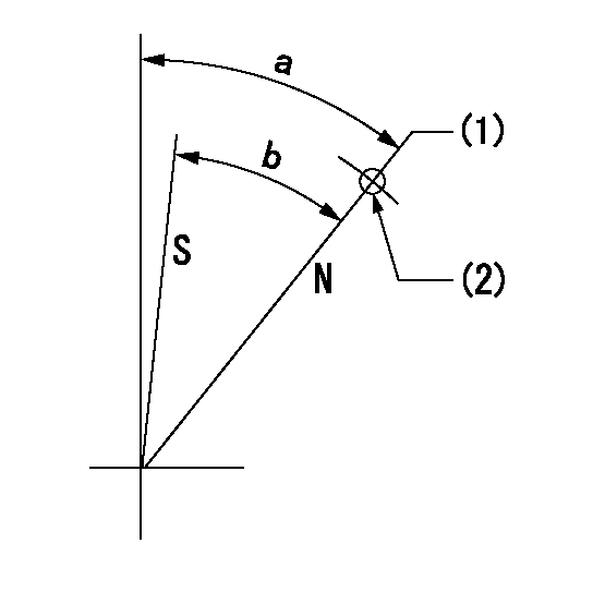
N:Pump normal
S:Stop the pump.
(1)Rack position = aa
(2)Use the pin at R = bb
----------
aa=R1(11)+-0.1mm bb=45mm
----------
a=(38.5deg)+-5deg b=34.5deg+-5deg
----------
aa=R1(11)+-0.1mm bb=45mm
----------
a=(38.5deg)+-5deg b=34.5deg+-5deg
Timing setting

(1)Pump vertical direction
(2)Coupling's key groove position at No 1 cylinder's beginning of injection
(3)-
(4)-
----------
----------
a=(20deg)
----------
----------
a=(20deg)
Information:
24Jun2016
U-330
A-250
D-292
O-288
Parts stock action only
PRODUCT IMPROVEMENT PROGRAM FOR INSPECTING AND POSSIBLY REMOVING 100-4721, 255-4533, AND 255-4534 INJECTOR WIRING HARNESSES FROM DEALER PARTS STOCK
7750 1408 1120 PI70631
Caterpillar’s obligations under this Service Letter are subject to, and shall not apply in contravention of, the laws, rules, regulations, directives, ordinances, orders, or statutes of the United States, or of any other applicable jurisdiction, without recourse or liability with respect to Caterpillar.
When submitting claim for Parts Stock Action, Use the appropriate 99Z as the s/n, the appropriate Service Letter Program Number as the Part number in the Part Causing Failure field, "7751" as the Group Number, "56" as the Description Code.
The information supplied in this service letter may not be valid after the termination date of this program.Do not perform the work outlined in this Service Letter after the termination date without first contacting your Caterpillar product analyst.
TERMINATION DATE
30Sep2016
PROBLEM
Certain 100-4721, 255-4533, and 255-4534 Injector Wiring Harnesses may have incorrect braiding used during manufacturing. The braiding can degrade over time, and flake off.
ACTION REQUIRED
Inspect all 100-4721, 255-4533, and 255-4534 Injector Wiring Harnesses in dealer parts stock.
Inspect 100-4721 Injector Wiring Harnesses for a silver dot on a injector connector. Refer to Image 1.
If a silver dot is present on an injector connector, then the harness is good. Mark the package as inspected per this program and return the part to dealer parts stock.
If there is no silver dot present on an injector connector, then remove the part from dealer parts stock.
Inspect 255-4533 and 255-4534 Injector Wiring Harnesses build date. Refer to Image 2 and Image 3.
If the harness does not have a build date between 8/5/15 and 4/7/16, with supplier code A0924Z0, then mark the package as inspected per this program and return the part to dealer parts stock.
If the harness does have a build date between 8/5/15 and 4/7/16, with supplier code A0924Z0, then remove the part from dealer parts stock.
Image1
Image2
Image3
SERVICE CLAIM ALLOWANCES
Submit one claim for all parts removed from dealer parts stock.
PARTS DISPOSITION
Handle the parts in accordance with your Warranty Bulletin on warranty parts handling.
Have questions with 106691-0550?
Group cross 106691-0550 ZEXEL
Nissan-Diesel
Nissan-Diesel
Nissan-Diesel
106691-0550
INJECTION-PUMP ASSEMBLY