Information injection-pump assembly
ZEXEL
106691-0530
1066910530
NISSAN-DIESEL
1679096565
1679096565

Rating:
Service parts 106691-0530 INJECTION-PUMP ASSEMBLY:
1.
_
7.
COUPLING PLATE
8.
_
9.
_
11.
Nozzle and Holder
16600-96511
12.
Open Pre:MPa(Kqf/cm2)
22.6{230}
15.
NOZZLE SET
Include in #1:
106691-0530
as INJECTION-PUMP ASSEMBLY
Cross reference number
ZEXEL
106691-0530
1066910530
NISSAN-DIESEL
1679096565
1679096565
Zexel num
Bosch num
Firm num
Name
106691-0530
1679096565 NISSAN-DIESEL
INJECTION-PUMP ASSEMBLY
PE6T * K
PE6T * K
Calibration Data:
Adjustment conditions
Test oil
1404 Test oil ISO4113 or {SAEJ967d}
1404 Test oil ISO4113 or {SAEJ967d}
Test oil temperature
degC
40
40
45
Nozzle and nozzle holder
105780-8140
Bosch type code
EF8511/9A
Nozzle
105780-0000
Bosch type code
DN12SD12T
Nozzle holder
105780-2080
Bosch type code
EF8511/9
Opening pressure
MPa
17.2
Opening pressure
kgf/cm2
175
Injection pipe
Outer diameter - inner diameter - length (mm) mm 8-3-600
Outer diameter - inner diameter - length (mm) mm 8-3-600
Overflow valve
132424-0620
Overflow valve opening pressure
kPa
157
123
191
Overflow valve opening pressure
kgf/cm2
1.6
1.25
1.95
Tester oil delivery pressure
kPa
157
157
157
Tester oil delivery pressure
kgf/cm2
1.6
1.6
1.6
Direction of rotation (viewed from drive side)
Right R
Right R
Injection timing adjustment
Direction of rotation (viewed from drive side)
Right R
Right R
Injection order
1-4-2-6-
3-5
Pre-stroke
mm
3.65
3.6
3.7
Beginning of injection position
Drive side NO.1
Drive side NO.1
Difference between angles 1
Cal 1-4 deg. 60 59.5 60.5
Cal 1-4 deg. 60 59.5 60.5
Difference between angles 2
Cyl.1-2 deg. 120 119.5 120.5
Cyl.1-2 deg. 120 119.5 120.5
Difference between angles 3
Cal 1-6 deg. 180 179.5 180.5
Cal 1-6 deg. 180 179.5 180.5
Difference between angles 4
Cal 1-3 deg. 240 239.5 240.5
Cal 1-3 deg. 240 239.5 240.5
Difference between angles 5
Cal 1-5 deg. 300 299.5 300.5
Cal 1-5 deg. 300 299.5 300.5
Injection quantity adjustment
Adjusting point
A
Rack position
9.3
Pump speed
r/min
650
650
650
Average injection quantity
mm3/st.
133.5
131.5
135.5
Max. variation between cylinders
%
0
-4
4
Basic
*
Fixing the lever
*
Boost pressure
kPa
28
28
Boost pressure
mmHg
210
210
Injection quantity adjustment_02
Adjusting point
C
Rack position
5.6+-0.5
Pump speed
r/min
370
370
370
Average injection quantity
mm3/st.
21
20
22
Max. variation between cylinders
%
0
-10
10
Fixing the rack
*
Boost pressure
kPa
0
0
0
Boost pressure
mmHg
0
0
0
Boost compensator adjustment
Pump speed
r/min
300
300
300
Rack position
9.2
Boost pressure
kPa
6.7
4
9.4
Boost pressure
mmHg
50
30
70
Boost compensator adjustment_02
Pump speed
r/min
300
300
300
Rack position
10+-0.1
Boost pressure
kPa
10.7
6.7
14.7
Boost pressure
mmHg
80
50
110
Boost compensator adjustment_03
Pump speed
r/min
300
300
300
Rack position
(10.6)
Boost pressure
kPa
14.7
14.7
14.7
Boost pressure
mmHg
110
110
110
Timer adjustment
Pump speed
r/min
900+80
Advance angle
deg.
0
0
0
Remarks
Start
Start
Timer adjustment_02
Pump speed
r/min
1080
Advance angle
deg.
1
0.5
1.5
Remarks
Finish
Finish
Test data Ex:
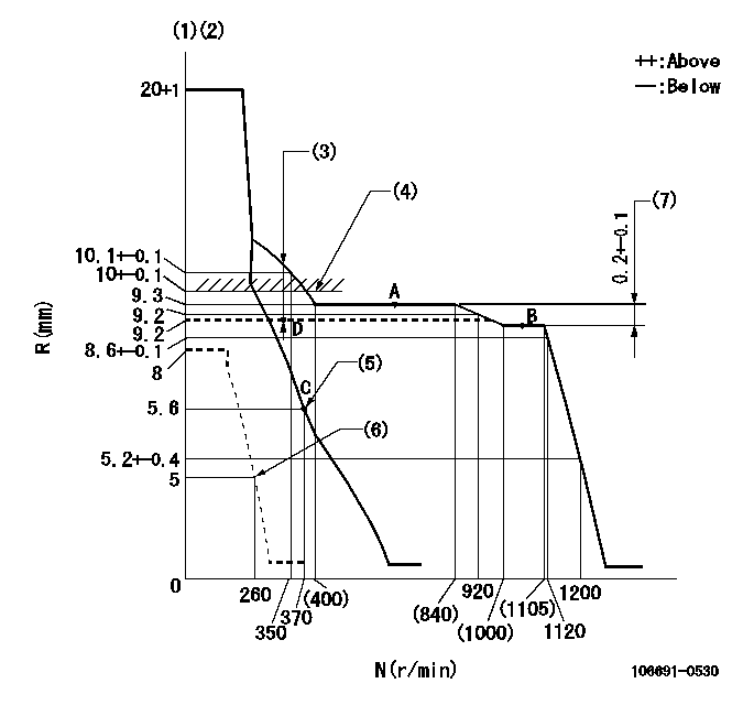
Governor adjustment

N:Pump speed
R:Rack position (mm)
(1)Target notch: K
(2)Tolerance for racks not indicated: +-0.05mm.
(3)Boost compensator stroke: BCL
(4)Excessive fuel lever setting (boost pressure 0)
(5)Main spring setting
(6)Set idle sub-spring
(7)Rack difference between N = N1 and N = N2
----------
K=17 BCL=(1.4)mm N1=1050r/min N2=650r/min
----------
----------
K=17 BCL=(1.4)mm N1=1050r/min N2=650r/min
----------
Speed control lever angle

F:Full speed
I:Idle
(1)Stopper bolt setting
----------
----------
a=(12deg)+-5deg b=(16deg)+-5deg
----------
----------
a=(12deg)+-5deg b=(16deg)+-5deg
Stop lever angle

N:Pump normal
S:Stop the pump.
----------
----------
a=26.5deg+-5deg b=53deg+-5deg
----------
----------
a=26.5deg+-5deg b=53deg+-5deg
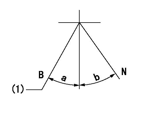
0000001101

N:Normal
B:When boosted
(1)Rack position = aa (at boost pressure = bb)
----------
aa=10+-0.1mm bb=0kPa(0mmHg)
----------
a=(8deg) b=(18deg)
----------
aa=10+-0.1mm bb=0kPa(0mmHg)
----------
a=(8deg) b=(18deg)
Timing setting

(1)Pump vertical direction
(2)Coupling's key groove position at No 1 cylinder's beginning of injection
(3)-
(4)-
----------
----------
a=(20deg)
----------
----------
a=(20deg)
Information:
Image1.2.1
Image1.2.2
Image1.2.3
3 - Using long straps and a crane, tilt the DOC on end so the outlet with the perforated plate end is facing up. With the DOC rotated on end, locate and center the drilling template and use C-Clamps to clamp the template in place so it does not shift.
With the DOC in this position ensure that all of the inside insulation pieces and the perforated plate are still in the correct position and in place.
Reference Image 1.3.1 and 1.3.2
Image1.3.1
Image1.3.2
4 - Position a mag base drill on the drilling template. While holding the inside perforated plate in position with a piece of 2" x 4" x 8' piece of lumber or other suitable size, drill the (4) 1.25" (31.75 mm) holes using a carbide tip cutter bit. Drill through the DOC end plate and insulation making sure the carbide tip cutter bit does NOT go through the perforated plate on the inside.
Note: A Hougen magnetic base drill works best for the drilling process and use a Hougen Copperhead Carbide Tip Annular Cutter bit. Hougen p/n 18240
Once the holes are drilled through clean out the drilled material.
Change out the carbide tip hole saw bit with a 3/8" drill bit. Ensure that the mag base drill stays in the same position so the 3/8" bit is drilling in the center of the 1.25" hole.
Note: The spacer can also be inserted in the 1.25" hole to use as a template to drill the 3/8" hole.
Drill a 3/8" hole through the inside perforated plate being careful not to drill too deep. From the outside end plate, the minimum drilling depth is 45 mm and the maximum drilling depth is 150 mm.
Note: This is a two person process with one person holding the inside perforated plate in place while the other person is drilling the holes. Additionally, the drilling through DOC should be done slowly as to not bend or drill through the perforated plate.
Reference Image 1.4.1 and 1.4.2
Image1.4.1
Image1.4.2
5 - Install the 1.25" spacer and slotted washer (Pacman washer) into each of the (4) drilled holes. The slotted washer will have to be angled in with needle nosed pliers and then moved in place in order to get it in the correct location. As an alternative to using needle nosed pliers, a thin wire tie can be tied around the slotted washer and lowered into the hole out of the way until it is re-positioned on top of the spacer.
Reference Images 1.5.1 and 1.5.2
Image1.5.1
Image1.5.2
6 - Once the spacer and slotted washer (Pacman washer) are installed in the DOC, install the 1.25" washer on top of the slotted washer. The 1.25" washer needs to be coated on both sides with Loctite 2620 sealant prior to installation.
From the outside of the DOC, install (2) each of the 3/8" bolt, small bolt washer, 2" washers and Graphite gasket through the holes in the slotted washers and spacers. On the inside of the DOC install an L Angle piece onto the lower 3/8" bolt threads and then
Have questions with 106691-0530?
Group cross 106691-0530 ZEXEL
Nissan-Diesel
Nissan-Diesel
106691-0530
1679096565
INJECTION-PUMP ASSEMBLY
PE6T
PE6T