Information injection-pump assembly
ZEXEL
106691-0490
1066910490
NISSAN-DIESEL
16713Z0003
16713z0003
Rating:
Cross reference number
ZEXEL
106691-0490
1066910490
NISSAN-DIESEL
16713Z0003
16713z0003
Zexel num
Bosch num
Firm num
Name
106691-0490
16713Z0003 NISSAN-DIESEL
INJECTION-PUMP ASSEMBLY
GD6T * K
GD6T * K
Calibration Data:
Adjustment conditions
Test oil
1404 Test oil ISO4113 or {SAEJ967d}
1404 Test oil ISO4113 or {SAEJ967d}
Test oil temperature
degC
40
40
45
Nozzle and nozzle holder
105780-8140
Bosch type code
EF8511/9A
Nozzle
105780-0000
Bosch type code
DN12SD12T
Nozzle holder
105780-2080
Bosch type code
EF8511/9
Opening pressure
MPa
17.2
Opening pressure
kgf/cm2
175
Injection pipe
Outer diameter - inner diameter - length (mm) mm 8-3-600
Outer diameter - inner diameter - length (mm) mm 8-3-600
Overflow valve opening pressure
kPa
157
123
191
Overflow valve opening pressure
kgf/cm2
1.6
1.25
1.95
Tester oil delivery pressure
kPa
157
157
157
Tester oil delivery pressure
kgf/cm2
1.6
1.6
1.6
Direction of rotation (viewed from drive side)
Right R
Right R
Injection timing adjustment
Direction of rotation (viewed from drive side)
Right R
Right R
Injection order
1-4-2-6-
3-5
Pre-stroke
mm
3.2
3.15
3.25
Beginning of injection position
Drive side NO.1
Drive side NO.1
Difference between angles 1
Cal 1-4 deg. 60 59.5 60.5
Cal 1-4 deg. 60 59.5 60.5
Difference between angles 2
Cyl.1-2 deg. 120 119.5 120.5
Cyl.1-2 deg. 120 119.5 120.5
Difference between angles 3
Cal 1-6 deg. 180 179.5 180.5
Cal 1-6 deg. 180 179.5 180.5
Difference between angles 4
Cal 1-3 deg. 240 239.5 240.5
Cal 1-3 deg. 240 239.5 240.5
Difference between angles 5
Cal 1-5 deg. 300 299.5 300.5
Cal 1-5 deg. 300 299.5 300.5
Injection quantity adjustment
Adjusting point
A
Rack position
10.2
Pump speed
r/min
650
650
650
Average injection quantity
mm3/st.
197
195
199
Max. variation between cylinders
%
0
-3
3
Basic
*
Fixing the lever
*
Boost pressure
kPa
21.3
21.3
Boost pressure
mmHg
160
160
Injection quantity adjustment_02
Adjusting point
B
Rack position
9.6
Pump speed
r/min
1050
1050
1050
Average injection quantity
mm3/st.
187
184
190
Max. variation between cylinders
%
0
-4
4
Fixing the lever
*
Boost pressure
kPa
21.3
21.3
Boost pressure
mmHg
160
160
Injection quantity adjustment_03
Adjusting point
C
Rack position
9
Pump speed
r/min
300
300
300
Average injection quantity
mm3/st.
158.7
154.7
162.7
Fixing the lever
*
Boost pressure
kPa
0
0
0
Boost pressure
mmHg
0
0
0
Injection quantity adjustment_04
Adjusting point
D
Rack position
5.6+-0.5
Pump speed
r/min
225
225
225
Average injection quantity
mm3/st.
20
17.6
22.4
Max. variation between cylinders
%
0
-15
15
Fixing the rack
*
Boost pressure
kPa
0
0
0
Boost pressure
mmHg
0
0
0
Boost compensator adjustment
Pump speed
r/min
300
300
300
Rack position
9
Boost pressure
kPa
4
2
4
Boost pressure
mmHg
30
15
30
Boost compensator adjustment_02
Pump speed
r/min
300
300
300
Rack position
10.2
Boost pressure
kPa
8
8
8
Boost pressure
mmHg
60
60
60
Timer adjustment
Pump speed
r/min
1150++
Advance angle
deg.
0
0
0
Remarks
Do not advance until starting N = 1150.
Do not advance until starting N = 1150.
Timer adjustment_02
Pump speed
r/min
-
Advance angle
deg.
1
1
1
Remarks
Measure the actual speed, stop
Measure the actual speed, stop
Test data Ex:
Governor adjustment
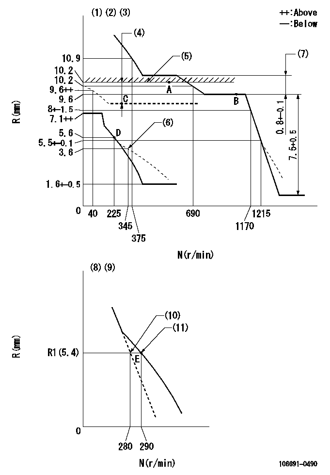
N:Pump speed
R:Rack position (mm)
(1)Lever ratio: RT
(2)Target shim dimension: TH
(3)Tolerance for racks not indicated: +-0.05mm.
(4)Boost compensator stroke: BCL
(5)Rack limit using stop lever
(6)Damper spring setting
(7)Rack difference between N = N1 and N = N2
(8)Variable speed specification: idling adjustment
(9)Fix the lever at the full-load position at delivery.
(10)Main spring setting
(11)Set idle sub-spring
----------
RT=1 TH=2.4mm BCL=1.2+-0.1mm N1=1050r/min N2=650r/min
----------
----------
RT=1 TH=2.4mm BCL=1.2+-0.1mm N1=1050r/min N2=650r/min
----------
Speed control lever angle
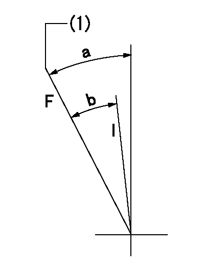
F:Full speed
I:Idle
(1)Set the stopper bolt (fixed at full-load position at delivery.)
----------
----------
a=(21deg)+-5deg b=(15deg)+-5deg
----------
----------
a=(21deg)+-5deg b=(15deg)+-5deg
0000000901
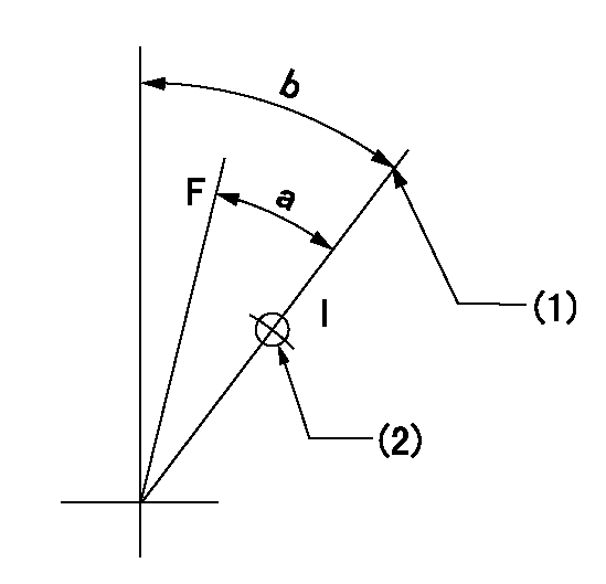
F:Full load
I:Idle
(1)Stopper bolt setting
(2)Use the hole at R = aa
----------
aa=43mm
----------
a=32.5deg+-3deg b=45deg+-5deg
----------
aa=43mm
----------
a=32.5deg+-3deg b=45deg+-5deg
Stop lever angle
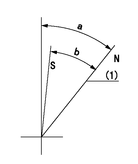
N:Pump normal
S:Stop the pump.
(1)Rack position = aa
----------
aa=10.2mm
----------
a=29deg+-5deg b=29deg+-5deg
----------
aa=10.2mm
----------
a=29deg+-5deg b=29deg+-5deg
Timing setting

(1)Pump vertical direction
(2)Coupling's key groove position at No 1 cylinder's beginning of injection
(3)-
(4)-
----------
----------
a=(10deg)
----------
----------
a=(10deg)
Information:
(1) Remove former fuel injection lines (1), the clamps and through-the-cover fuel line adapters (2) from the engine; these parts will not be needed again. Install 8M4437 Seals on twelve 1W6777 Adapters (3). Put engine oil on the seals and install the adapters in valve cover base assemblies (4) where adapters (2) were removed. Fasten the adapters to bases (4) with two 5N5365 Locks on each and the former nuts. Connect former fuel lines (5) to adapters (3) and the former fuel nozzle adapters. (2) Install a 2W2500 Washer (7) and a 6V6579 Seal (8) on each adapter (3). Install a 5P9267 Seal on each injector pump; put diesel fuel on the seals before installation. Loosely install fuel injection line assemblies: number "6" (9), number "12" (10), number "4" (11), number "2" (12), number "10" (13) and number "8" (14) on the right side of the engine between the fuel injection pumps and adapters (3). See the above chart for the correct part number of the fuel lines. Remove two bolts and install 5N5370 Bracket (15) and 5N5374 Clamp (16) where the bolts were removed. Fasten the fuel injection lines to bracket (15) with two 5N5369 Dampers, a 5N5371 Clamp and two 2W7884 Bolt Assemblies. Fasten the fuel injection lines to clamp (16) with two 5N5373 Dampers, a 5N5372 Clamp and two 2W7884 Bolts. Use 5N5957 and 5N5958 Clamps, two 5N5956 Dampers and a 2W7884 Bolt Assembly to fasten the fuel lines together at (A). Use 5N5376 and 5N5377 Clamps, two 5N5375 Dampers and three 2W7884 Bolt Assemblies to fasten the fuel lines together at (B). Tighten the bolt assemblies to 10 N m (7 lb.ft.) torque. Tighten nuts (17) on each end of the fuel injection lines to 40 7 N m (35 5 lb.ft.) torque, then tighten nuts (18).(3) Loosely install fuel injection line assemblies; number "11" (19), number "3" (20), number "7" (21), number "9" (22), number "5" (23) and number "1" (24) on the left side of the engine between adapters (3) and the fuel injection pump as shown. Remove a bolt and install 5N5370 Bracket (25) where the bolt was removed. Fasten the fuel lines to bracket (25) with two 5N5369 Dampers, a 5N5371 Clamp and two 2W7884 Bolts. On engines equipped with aftercooler, fasten 5N5379 Plate (26) to an existing bolt on the aftercooler. Fasten the fuel injection lines to plate (26) with two 5N5378 Dampers, a 5N5374 Clamp and two 2W7884 Bolt Assemblies. Use two 5N5376 and 5N5377 Clamps, four 5N5375 Dampers and four 2W7884 Bolt Assemblies to fasten the fuel lines together at locations (C). If the engine does not have an aftercooler, use 5N5957 and 5N5958 Clamps, two 5N5956 Dampers and a 2W7884 Bolt Assembly to fasten the fuel injection lines together at (D). Tighten the fuel lines as shown in step 2.2W5100 Fuel Lines Drain Group
(1) Install a 9L8496 Tee (1) in each adapter (2). Connect tees (1) together with ten 5N5940 Tube Assemblies (3).
(1) Install a 9L8496 Tee (1) in each adapter (2). Connect tees (1) together with ten 5N5940 Tube Assemblies (3).
Have questions with 106691-0490?
Group cross 106691-0490 ZEXEL
Nissan-Diesel
Nissan-Diesel
Nissan-Diesel
Nissan-Diesel
Nissan-Diesel
Nissan-Diesel
Nissan-Diesel
Nissan-Diesel
Nissan-Diesel
106691-0490
16713Z0003
INJECTION-PUMP ASSEMBLY
GD6T
GD6T