Information injection-pump assembly
ZEXEL
106691-0440
1066910440
Rating:
Service parts 106691-0440 INJECTION-PUMP ASSEMBLY:
1.
_
7.
COUPLING PLATE
8.
_
9.
_
11.
Nozzle and Holder
16600-96572
12.
Open Pre:MPa(Kqf/cm2)
14.7{150}/19.6{200}
15.
NOZZLE SET
Include in #1:
106691-0440
as INJECTION-PUMP ASSEMBLY
Cross reference number
ZEXEL
106691-0440
1066910440
Zexel num
Bosch num
Firm num
Name
106691-0440
INJECTION-PUMP ASSEMBLY
Calibration Data:
Adjustment conditions
Test oil
1404 Test oil ISO4113 or {SAEJ967d}
1404 Test oil ISO4113 or {SAEJ967d}
Test oil temperature
degC
40
40
45
Nozzle and nozzle holder
105780-8140
Bosch type code
EF8511/9A
Nozzle
105780-0000
Bosch type code
DN12SD12T
Nozzle holder
105780-2080
Bosch type code
EF8511/9
Opening pressure
MPa
17.2
Opening pressure
kgf/cm2
175
Injection pipe
Outer diameter - inner diameter - length (mm) mm 8-3-600
Outer diameter - inner diameter - length (mm) mm 8-3-600
Overflow valve opening pressure
kPa
157
123
191
Overflow valve opening pressure
kgf/cm2
1.6
1.25
1.95
Tester oil delivery pressure
kPa
157
157
157
Tester oil delivery pressure
kgf/cm2
1.6
1.6
1.6
Direction of rotation (viewed from drive side)
Right R
Right R
Injection timing adjustment
Direction of rotation (viewed from drive side)
Right R
Right R
Injection order
1-4-2-6-
3-5
Pre-stroke
mm
3.65
3.6
3.7
Beginning of injection position
Drive side NO.1
Drive side NO.1
Difference between angles 1
Cal 1-4 deg. 60 59.5 60.5
Cal 1-4 deg. 60 59.5 60.5
Difference between angles 2
Cyl.1-2 deg. 120 119.5 120.5
Cyl.1-2 deg. 120 119.5 120.5
Difference between angles 3
Cal 1-6 deg. 180 179.5 180.5
Cal 1-6 deg. 180 179.5 180.5
Difference between angles 4
Cal 1-3 deg. 240 239.5 240.5
Cal 1-3 deg. 240 239.5 240.5
Difference between angles 5
Cal 1-5 deg. 300 299.5 300.5
Cal 1-5 deg. 300 299.5 300.5
Injection quantity adjustment
Adjusting point
A
Rack position
7.6
Pump speed
r/min
650
650
650
Average injection quantity
mm3/st.
123.8
121.8
125.8
Max. variation between cylinders
%
0
-4
4
Basic
*
Fixing the lever
*
Injection quantity adjustment_02
Adjusting point
C
Rack position
4.9+-0.5
Pump speed
r/min
225
225
225
Average injection quantity
mm3/st.
8
6.7
9.3
Max. variation between cylinders
%
0
-10
10
Fixing the rack
*
Injection quantity adjustment_03
Adjusting point
E
Rack position
R1(9.4)+
-0.1
Pump speed
r/min
40
40
40
Average injection quantity
mm3/st.
91
91
101
Fixing the lever
*
Rack limit
*
Timer adjustment
Pump speed
r/min
950
Remarks
Measure the actual advance angle.
Measure the actual advance angle.
Timer adjustment_02
Pump speed
r/min
1050
Advance angle
deg.
5
4.5
5.5
Remarks
Finish
Finish
Test data Ex:
Governor adjustment
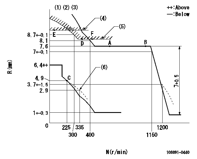
N:Pump speed
R:Rack position (mm)
(1)Lever ratio: RT
(2)Target shim dimension: TH
(3)Tolerance for racks not indicated: +-0.05mm.
(4)Rack limit using stop lever: RA
(5)Excess fuel setting for starting: SXL
(6)Damper spring setting
----------
RT=1 TH=1.8mm RA=R1(9.4)+-0.1mm SXL=8.4+-0.1mm
----------
----------
RT=1 TH=1.8mm RA=R1(9.4)+-0.1mm SXL=8.4+-0.1mm
----------
Speed control lever angle

F:Full speed
----------
----------
a=16deg+-5deg
----------
----------
a=16deg+-5deg
0000000901

F:Full load
I:Idle
(1)Stopper bolt setting
----------
----------
a=15deg+-5deg b=24deg+-3deg
----------
----------
a=15deg+-5deg b=24deg+-3deg
Stop lever angle
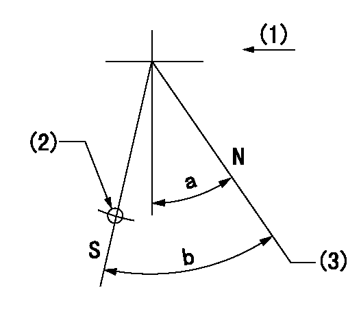
N:Pump normal
S:Stop the pump.
(1)Drive side
(2)Use the hole at R = aa
(3)Rack position bb
----------
aa=50mm bb=(9.4)+-0.1mm
----------
a=22deg+-5deg b=24deg+-5deg
----------
aa=50mm bb=(9.4)+-0.1mm
----------
a=22deg+-5deg b=24deg+-5deg
Timing setting

(1)Pump vertical direction
(2)Coupling's key groove position at No 1 cylinder's beginning of injection
(3)-
(4)-
----------
----------
a=(20deg)
----------
----------
a=(20deg)
Information:
(1) Thickness of spacer plate ... 8.585 0.025 mm (.3379 .0009 in)Thickness of gasket that is placed between spacer plate and cylinder block ... 0.208 0.025 mm (.0081 .0009)Height of liner over spacer plate, under installation pressure ... 0.13 0.08 mm (.005 .003 in)(2) Height of four dowels above top surface of cylinder block:End dowels (Put 7M7456 Bearing Mount Compound on two end dowels at installation) ... 18.5 0.5 mm (.73 .02 in)Middle dowels ... 16.0 0.5 mm (.63 .02 in)(3)
Have questions with 106691-0440?
Group cross 106691-0440 ZEXEL
Nissan-Diesel
Nissan-Diesel
Nissan-Diesel
Nissan-Diesel
106691-0440
INJECTION-PUMP ASSEMBLY