Information injection-pump assembly
BOSCH
9 400 617 761
9400617761
ZEXEL
106691-0423
1066910423
NISSAN-DIESEL
1671396869
1671396869
Rating:
Service parts 106691-0423 INJECTION-PUMP ASSEMBLY:
1.
_
7.
COUPLING PLATE
8.
_
9.
_
11.
Nozzle and Holder
1660096574
12.
Open Pre:MPa(Kqf/cm2)
14.7(150)/19.6(200)
15.
NOZZLE SET
Include in #1:
106691-0423
as INJECTION-PUMP ASSEMBLY
Cross reference number
BOSCH
9 400 617 761
9400617761
ZEXEL
106691-0423
1066910423
NISSAN-DIESEL
1671396869
1671396869
Zexel num
Bosch num
Firm num
Name
106691-0423
9 400 617 761
1671396869 NISSAN-DIESEL
INJECTION-PUMP ASSEMBLY
PF6 * K
PF6 * K
Calibration Data:
Adjustment conditions
Test oil
1404 Test oil ISO4113 or {SAEJ967d}
1404 Test oil ISO4113 or {SAEJ967d}
Test oil temperature
degC
40
40
45
Nozzle and nozzle holder
105780-8140
Bosch type code
EF8511/9A
Nozzle
105780-0000
Bosch type code
DN12SD12T
Nozzle holder
105780-2080
Bosch type code
EF8511/9
Opening pressure
MPa
17.2
Opening pressure
kgf/cm2
175
Injection pipe
Outer diameter - inner diameter - length (mm) mm 8-3-600
Outer diameter - inner diameter - length (mm) mm 8-3-600
Overflow valve opening pressure
kPa
157
123
191
Overflow valve opening pressure
kgf/cm2
1.6
1.25
1.95
Tester oil delivery pressure
kPa
157
157
157
Tester oil delivery pressure
kgf/cm2
1.6
1.6
1.6
Direction of rotation (viewed from drive side)
Right R
Right R
Injection timing adjustment
Direction of rotation (viewed from drive side)
Right R
Right R
Injection order
1-4-2-6-
3-5
Pre-stroke
mm
3.65
3.6
3.7
Rack position
Point A R=A
Point A R=A
Beginning of injection position
Drive side NO.1
Drive side NO.1
Difference between angles 1
Cal 1-4 deg. 60 59.5 60.5
Cal 1-4 deg. 60 59.5 60.5
Difference between angles 2
Cyl.1-2 deg. 120 119.5 120.5
Cyl.1-2 deg. 120 119.5 120.5
Difference between angles 3
Cal 1-6 deg. 180 179.5 180.5
Cal 1-6 deg. 180 179.5 180.5
Difference between angles 4
Cal 1-3 deg. 240 239.5 240.5
Cal 1-3 deg. 240 239.5 240.5
Difference between angles 5
Cal 1-5 deg. 300 299.5 300.5
Cal 1-5 deg. 300 299.5 300.5
Injection quantity adjustment
Adjusting point
A
Rack position
8.3
Pump speed
r/min
650
650
650
Average injection quantity
mm3/st.
126.3
124.3
128.3
Max. variation between cylinders
%
0
-4
4
Basic
*
Fixing the lever
*
Remarks
Startup boost setting
Startup boost setting
Injection quantity adjustment_02
Adjusting point
C
Rack position
5.1+-0.5
Pump speed
r/min
225
225
225
Average injection quantity
mm3/st.
8
6.7
9.3
Max. variation between cylinders
%
0
-10
10
Fixing the rack
*
Timer adjustment
Pump speed
r/min
950
Remarks
Measure the actual advance angle.
Measure the actual advance angle.
Timer adjustment_02
Pump speed
r/min
1050
Advance angle
deg.
5
4.5
5.5
Remarks
Finish
Finish
Test data Ex:
Governor adjustment
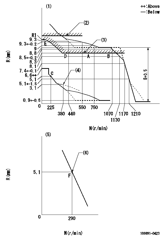
N:Pump speed
R:Rack position (mm)
(1)Tolerance for racks not indicated: +-0.05mm.
(2)Rack limit using the stop lever: R1
(3)Excess fuel setting for starting
(4)Damper spring setting
(5)Variable speed specification: idling adjustment
(6)Main spring setting
----------
R1=11.8+0.2mm
----------
----------
R1=11.8+0.2mm
----------
Speed control lever angle

F:Full speed
I:Idle
(1)Speed = aa (point F)
(2)Stopper bolt setting
----------
aa=290r/min
----------
a=3.5deg+-5deg b=13.5deg+-5deg
----------
aa=290r/min
----------
a=3.5deg+-5deg b=13.5deg+-5deg
0000000901

F:Full load
I:Idle
(1)Stopper bolt setting
(2)At threaded hole above R = aa
----------
aa=17mm
----------
a=15deg+-5deg b=29deg+-3deg
----------
aa=17mm
----------
a=15deg+-5deg b=29deg+-3deg
Stop lever angle

N:Pump normal
S:Stop the pump.
(1)Rack position = aa
----------
aa=11.8+0.2mm
----------
a=35deg+-5deg b=35deg+-5deg
----------
aa=11.8+0.2mm
----------
a=35deg+-5deg b=35deg+-5deg
Timing setting

(1)Pump vertical direction
(2)Coupling's key groove position at No 1 cylinder's beginning of injection
(3)At rack position = aa
(4)-
----------
aa=R1(11.2)mm
----------
a=(30deg)
----------
aa=R1(11.2)mm
----------
a=(30deg)
Information:
(1) Bore in rocker arm for shaft ... 24.803 0.013 mm (.9765 .0005 in) Diameter of rocker arm shaft ... 24.752 0.013 mm (.9745 .0005 in)(2) Put 5P3931 Anti-Seize Compound on all the threads of bolts that hold rocker arm shafts and tighten the bolts in the step sequence that follows: 1. Tighten bolts from 1 through 6 in number sequence to ... 270 27 N m (200 20 lb ft)2. Tighten bolts from 1 through 6 in number sequence to ... 450 20 N m (330 15 lb ft)3. Tighten bolts from 1 through 6 in number sequence again to ... 450 20 N m (330 15 lb ft)(3) Torque for locknut for valve adjustment screw ... 30 4 N m (22 3 lb ft)(4) Torque for locknut for bridge adjustment screw ... 30 4 N m (22 3 lb ft)(5) Valve lash: Inlet valves ... .38 0.1 mm (.015 .004 in)Exhaust valves ... 0.76 0.1 mm (.03 .004 in)(6) Height to top of dowel ... 53.3 0.5 mm (2.10 .02 in)(7) Diameter of dowel ... 11.008 0.003 mm (.4334 .0001 in) Bore in bridge for dowel ... 11.13 0.05 mm (.438 .002 in)Bore in head for dowel ... 10.968 0.020 mm (.4318 .0008 in)(8) Diameter of valve lifter ... 27.896 0.013 mm (1.0983 .0005 in) Bore in block for valve lifter ... 27.953 0.019 mm (1.1005 .0008 in) See Guideline For Reusable Parts; Salvage Of Lifter Bores In 3400 Family Engines, SEBF8069 for the procedure, tooling and specifications needed to install 4W4588 Sleeves for salvage of the lifter bores in the cylinder block.(9) Guide springs must not be used again. Always install new guide springs. (10) 2N7229 Spring: Length under test force ... 74.2 mm (2.92 in)Test force ... 45 to 53 N (10 to 12 lb)Free length after test ... 114.3 mm (4.50 in)Outside diameter ... 29.7 mm (1.17 in)(11) Dowel length above top surface of rocker shaft support to be ... 12.7 1.0 mm (.50 .04 in)(12) Clearance for rocker arms (both ends) ... 0.30 to 1.40 mm (.012 to .055 in)(13) Use 2N7228 Washer as needed to get clearance (12). There must be a minimum of one 2N7228 Washer at each end of the rocker arm shaft. The bridge should be checked and/or adjusted each time the valves are adjusted. To check for wear use a dial indicator to measure the amount of wear on the bridge seat. Make sure the contact point on the dial indicator is small enough in diameter to get an accurate measurement. (A) Minimum dimension after reconditioning ... 16.89 mm (.665 in)(B) Allowable wear before reconditioning ... 0.13 mm (.005 in).Inspect the bridge
Have questions with 106691-0423?
Group cross 106691-0423 ZEXEL
Nissan-Diesel
Nissan-Diesel
Nissan-Diesel
106691-0423
9 400 617 761
1671396869
INJECTION-PUMP ASSEMBLY
PF6
PF6