Information injection-pump assembly
BOSCH
F 019 Z10 641
f019z10641
ZEXEL
106691-0290
1066910290
Rating:
Service parts 106691-0290 INJECTION-PUMP ASSEMBLY:
1.
_
7.
COUPLING PLATE
8.
_
9.
_
11.
Nozzle and Holder
16600Z001
12.
Open Pre:MPa(Kqf/cm2)
22.6(230)
15.
NOZZLE SET
Include in #1:
106691-0290
as INJECTION-PUMP ASSEMBLY
Cross reference number
BOSCH
F 019 Z10 641
f019z10641
ZEXEL
106691-0290
1066910290
Zexel num
Bosch num
Firm num
Name
Calibration Data:
Adjustment conditions
Test oil
1404 Test oil ISO4113 or {SAEJ967d}
1404 Test oil ISO4113 or {SAEJ967d}
Test oil temperature
degC
40
40
45
Nozzle and nozzle holder
105780-8140
Bosch type code
EF8511/9A
Nozzle
105780-0000
Bosch type code
DN12SD12T
Nozzle holder
105780-2080
Bosch type code
EF8511/9
Opening pressure
MPa
17.2
Opening pressure
kgf/cm2
175
Injection pipe
Outer diameter - inner diameter - length (mm) mm 8-3-600
Outer diameter - inner diameter - length (mm) mm 8-3-600
Overflow valve opening pressure
kPa
157
123
191
Overflow valve opening pressure
kgf/cm2
1.6
1.25
1.95
Tester oil delivery pressure
kPa
157
157
157
Tester oil delivery pressure
kgf/cm2
1.6
1.6
1.6
Direction of rotation (viewed from drive side)
Right R
Right R
Injection timing adjustment
Direction of rotation (viewed from drive side)
Right R
Right R
Injection order
1-4-2-6-
3-5
Pre-stroke
mm
3.2
3.15
3.25
Beginning of injection position
Drive side NO.1
Drive side NO.1
Difference between angles 1
Cal 1-4 deg. 60 59.5 60.5
Cal 1-4 deg. 60 59.5 60.5
Difference between angles 2
Cyl.1-2 deg. 120 119.5 120.5
Cyl.1-2 deg. 120 119.5 120.5
Difference between angles 3
Cal 1-6 deg. 180 179.5 180.5
Cal 1-6 deg. 180 179.5 180.5
Difference between angles 4
Cal 1-3 deg. 240 239.5 240.5
Cal 1-3 deg. 240 239.5 240.5
Difference between angles 5
Cal 1-5 deg. 300 299.5 300.5
Cal 1-5 deg. 300 299.5 300.5
Injection quantity adjustment
Adjusting point
A
Rack position
10.2
Pump speed
r/min
650
650
650
Average injection quantity
mm3/st.
197
195
199
Max. variation between cylinders
%
0
-3
3
Basic
*
Fixing the lever
*
Boost pressure
kPa
21.3
21.3
Boost pressure
mmHg
160
160
Injection quantity adjustment_02
Adjusting point
B
Rack position
9.6
Pump speed
r/min
1050
1050
1050
Average injection quantity
mm3/st.
187
184
190
Max. variation between cylinders
%
0
-4
4
Fixing the lever
*
Boost pressure
kPa
21.3
21.3
Boost pressure
mmHg
160
160
Injection quantity adjustment_03
Adjusting point
C
Rack position
9
Pump speed
r/min
300
300
300
Average injection quantity
mm3/st.
158.7
154.7
162.7
Fixing the lever
*
Boost pressure
kPa
0
0
0
Boost pressure
mmHg
0
0
0
Injection quantity adjustment_04
Adjusting point
D
Rack position
5.6+-0.5
Pump speed
r/min
225
225
225
Average injection quantity
mm3/st.
20
17.6
22.4
Max. variation between cylinders
%
0
-15
15
Fixing the rack
*
Boost pressure
kPa
0
0
0
Boost pressure
mmHg
0
0
0
Boost compensator adjustment
Pump speed
r/min
300
300
300
Rack position
9
Boost pressure
kPa
4
2
4
Boost pressure
mmHg
30
15
30
Boost compensator adjustment_02
Pump speed
r/min
300
300
300
Rack position
10.2
Boost pressure
kPa
8
8
8
Boost pressure
mmHg
60
60
60
Timer adjustment
Pump speed
r/min
1150
Advance angle
deg.
0.5
Timer adjustment_02
Pump speed
r/min
-
Advance angle
deg.
1
1
1
Remarks
Measure the actual speed, stop
Measure the actual speed, stop
Test data Ex:
Governor adjustment
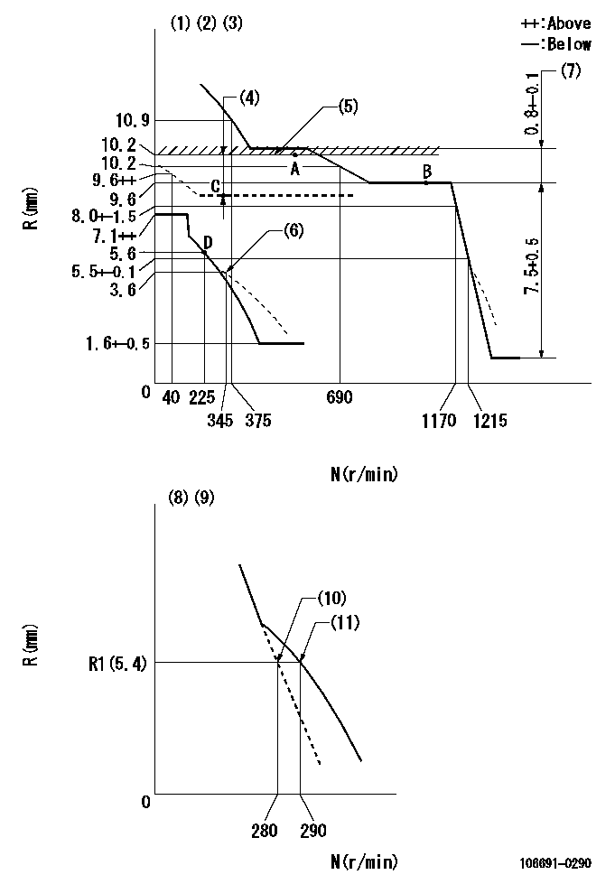
N:Pump speed
R:Rack position (mm)
(1)Lever ratio: RT
(2)Target shim dimension: TH
(3)Tolerance for racks not indicated: +-0.05mm.
(4)Boost compensator stroke: BCL
(5)Rack limit using stop lever
(6)Damper spring setting
(7)Rack difference between N = N1 and N = N2
(8)Variable speed specification: idling adjustment
(9)Fix the lever at the full-load position at delivery.
(10)Main spring setting
(11)Set idle sub-spring
----------
RT=1 TH=2.1mm BCL=1.2+-0.1mm N1=1050r/min N2=650r/min
----------
----------
RT=1 TH=2.1mm BCL=1.2+-0.1mm N1=1050r/min N2=650r/min
----------
Speed control lever angle
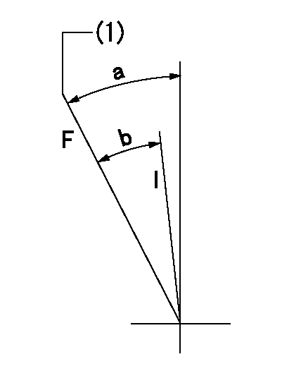
F:Full speed
I:Idle
(1)Set the stopper bolt (fixed at full-load position at delivery.)
----------
----------
a=(21deg)+-5deg b=(15deg)+-5deg
----------
----------
a=(21deg)+-5deg b=(15deg)+-5deg
0000000901

F:Full load
I:Idle
(1)Stopper bolt setting
(2)At threaded hole above R = aa
----------
aa=17mm
----------
a=15deg+-5deg b=32.5deg+-3deg
----------
aa=17mm
----------
a=15deg+-5deg b=32.5deg+-3deg
Stop lever angle
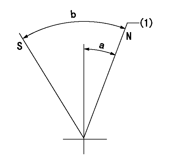
N:Pump normal
S:Stop the pump.
(1)Rack position = aa
----------
aa=10.2mm
----------
a=11deg+-5deg b=29deg+-5deg
----------
aa=10.2mm
----------
a=11deg+-5deg b=29deg+-5deg
Timing setting

(1)Pump vertical direction
(2)Coupling's key groove position at No 1 cylinder's beginning of injection
(3)-
(4)-
----------
----------
a=(10deg)
----------
----------
a=(10deg)
Information:
Start By:a. remove valve cover 1. Remove four bolts (1) that hold each rocker arm assembly in position. Remove the rocker arm assemblies from the engine.2. Put identification marks on all push rods as to their location in the engine. Remove the push rods from the engine. 3. Disassemble the rocker arm assemblies as follows: a. Remove the pin and rocker arm mounts (2). Remove the two rocker arm assemblies and the unit injector arm assembly from the shaft assembly.b. Remove the nut and valve adjusting screw (3) from each rocker arm.c. Remove arm button (7), retaining ring (6) and the arm socket from the unit injector arm.d. Loosen the nut, and remove injection adjusting screw (4) from the unit injector arm.e. Remove sleeve bearing (5) from the unit injector arm. The following steps are for the installation of the rocker arm assemblies and push rods.4. Be sure all parts of the rocker arm assemblies are clean.5. Assemble the rocker arm assemblies as follows: a. Install sleeve bearing (5) in the unit injector arm with Tool (A).b. Install injection adjusting screw (4) and the nut in the unit injector arm.c. Install the arm socket, retaining ring (6) and arm button (7) in the unit injector arm.d. Install valve adjusting screw (3) and the nut in each rocker arm.e. Put the rocker arm assemblies and the unit injector arm assembly in position on the shaft assembly. Install two rocker arm mounts (2) and the pins that hold them.6. Apply clean engine oil to the push rods, and install them in their original locations in the engine. Be sure the push rods are seated in the lifter arm assemblies.7. Loosen all adjusting screws in the rocker arm assemblies. Position the rocker arm assemblies on the cylinder head assembly, and install bolts (1) that hold them in position.8. Adjust the fuel timing and the valve lash. See the topics "Fuel Timing" & "Valve Lash" in the 3114 & 3116 Diesel truck Engines Systems Operation & Testing & Adjusting module, Form No. SENR6437.End By:a. install valve cover