Information injection-pump assembly
BOSCH
9 400 617 749
9400617749
ZEXEL
106691-0203
1066910203
NISSAN-DIESEL
1671396671
1671396671
Rating:
Cross reference number
BOSCH
9 400 617 749
9400617749
ZEXEL
106691-0203
1066910203
NISSAN-DIESEL
1671396671
1671396671
Zexel num
Bosch num
Firm num
Name
106691-0203
9 400 617 749
1671396671 NISSAN-DIESEL
INJECTION-PUMP ASSEMBLY
PE6T * K
PE6T * K
Calibration Data:
Adjustment conditions
Test oil
1404 Test oil ISO4113 or {SAEJ967d}
1404 Test oil ISO4113 or {SAEJ967d}
Test oil temperature
degC
40
40
45
Nozzle and nozzle holder
105780-8140
Bosch type code
EF8511/9A
Nozzle
105780-0000
Bosch type code
DN12SD12T
Nozzle holder
105780-2080
Bosch type code
EF8511/9
Opening pressure
MPa
17.2
Opening pressure
kgf/cm2
175
Injection pipe
Outer diameter - inner diameter - length (mm) mm 8-3-600
Outer diameter - inner diameter - length (mm) mm 8-3-600
Overflow valve (drive side)
134424-1720
Overflow valve opening pressure (drive side)
kPa
162
147
177
Overflow valve opening pressure (drive side)
kgf/cm2
1.65
1.5
1.8
Overflow valve (governor side)
132424-0620
Overflow valve opening pressure (governor side)
kPa
157
123
191
Overflow valve opening pressure (governor side)
kgf/cm2
1.6
1.25
1.95
Tester oil delivery pressure
kPa
157
157
157
Tester oil delivery pressure
kgf/cm2
1.6
1.6
1.6
Direction of rotation (viewed from drive side)
Right R
Right R
Injection timing adjustment
Direction of rotation (viewed from drive side)
Right R
Right R
Injection order
1-4-2-6-
3-5
Pre-stroke
mm
3.65
3.6
3.7
Beginning of injection position
Drive side NO.1
Drive side NO.1
Difference between angles 1
Cal 1-4 deg. 60 59.5 60.5
Cal 1-4 deg. 60 59.5 60.5
Difference between angles 2
Cyl.1-2 deg. 120 119.5 120.5
Cyl.1-2 deg. 120 119.5 120.5
Difference between angles 3
Cal 1-6 deg. 180 179.5 180.5
Cal 1-6 deg. 180 179.5 180.5
Difference between angles 4
Cal 1-3 deg. 240 239.5 240.5
Cal 1-3 deg. 240 239.5 240.5
Difference between angles 5
Cal 1-5 deg. 300 299.5 300.5
Cal 1-5 deg. 300 299.5 300.5
Injection quantity adjustment
Adjusting point
A
Rack position
11.1
Pump speed
r/min
650
650
650
Average injection quantity
mm3/st.
162
160
164
Max. variation between cylinders
%
0
-4
4
Basic
*
Fixing the lever
*
Boost pressure
kPa
30.7
30.7
Boost pressure
mmHg
230
230
Injection quantity adjustment_02
Adjusting point
B
Rack position
10.8+-0.
5
Pump speed
r/min
1100
1100
1100
Average injection quantity
mm3/st.
162.2
159.2
165.2
Max. variation between cylinders
%
0
-4
4
Fixing the lever
*
Boost pressure
kPa
30.7
30.7
Boost pressure
mmHg
230
230
Injection quantity adjustment_03
Adjusting point
C
Rack position
6+-0.5
Pump speed
r/min
250
250
250
Average injection quantity
mm3/st.
13.2
12.2
14.2
Max. variation between cylinders
%
0
-10
10
Fixing the rack
*
Boost pressure
kPa
0
0
0
Boost pressure
mmHg
0
0
0
Injection quantity adjustment_04
Adjusting point
D
Rack position
R1(9.5)
Pump speed
r/min
300
300
300
Average injection quantity
mm3/st.
112
109
115
Max. variation between cylinders
%
0
-4
4
Fixing the lever
*
Boost pressure
kPa
0
0
0
Boost pressure
mmHg
0
0
0
Boost compensator adjustment
Pump speed
r/min
300
300
300
Rack position
R1(9.5)
Boost pressure
kPa
6.7
4
6.7
Boost pressure
mmHg
50
30
50
Boost compensator adjustment_02
Pump speed
r/min
300
300
300
Rack position
11.7
Boost pressure
kPa
24
Boost pressure
mmHg
180
Timer adjustment
Pump speed
r/min
200+100
Advance angle
deg.
1.6
1.1
2.1
Remarks
Start
Start
Timer adjustment_02
Pump speed
r/min
500-150
Advance angle
deg.
0
0
0
Timer adjustment_03
Pump speed
r/min
910+80
Advance angle
deg.
0
0
0
Timer adjustment_04
Pump speed
r/min
(1050)
Advance angle
deg.
2
1.5
2.5
Remarks
Finish
Finish
Test data Ex:
Governor adjustment
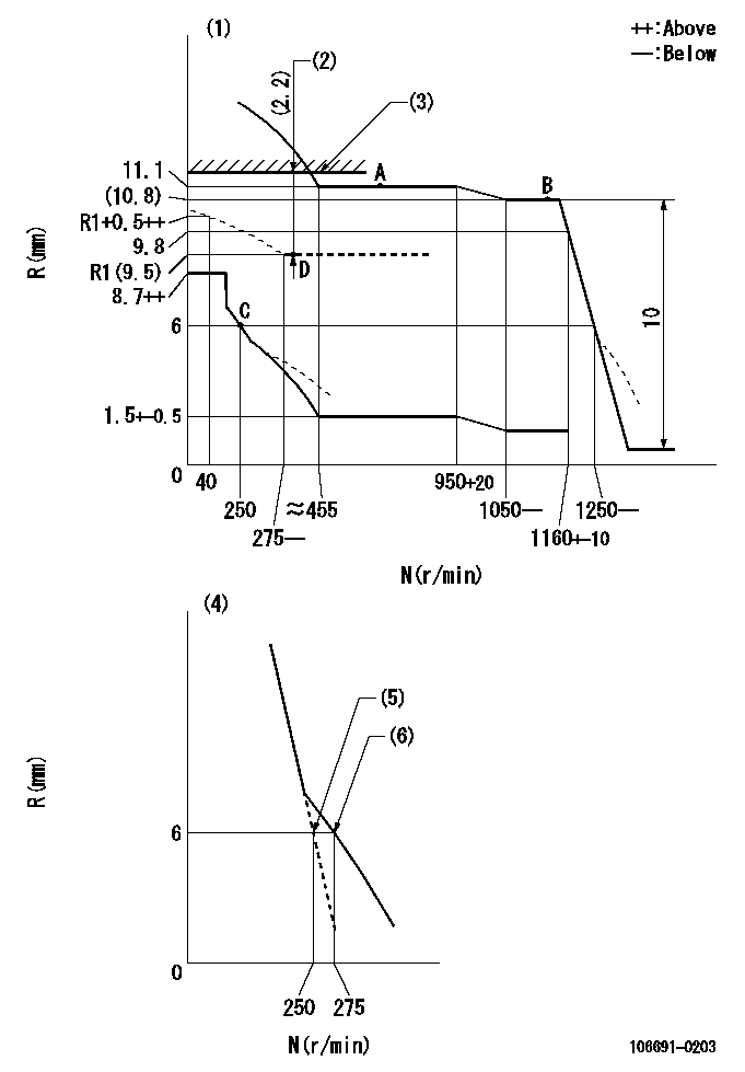
N:Pump speed
R:Rack position (mm)
(1)Damper spring setting: DL
(2)Boost compensator stroke
(3)Rack limit using the stop lever: R1
(4)Variable speed specification.
(5)Main spring setting
(6)Set idle sub-spring
----------
DL=5-0.2mm R1=11.7+-0.1mm
----------
----------
DL=5-0.2mm R1=11.7+-0.1mm
----------
Speed control lever angle

F:Full speed
I:Idle
(1)Stopper bolt setting
----------
----------
a=10deg+-5deg b=26deg+-5deg
----------
----------
a=10deg+-5deg b=26deg+-5deg
0000000901

F:Full load
I:Idle
(1)Stopper bolt setting
----------
----------
a=20.5deg+-5deg b=35deg+-3deg
----------
----------
a=20.5deg+-5deg b=35deg+-3deg
Stop lever angle
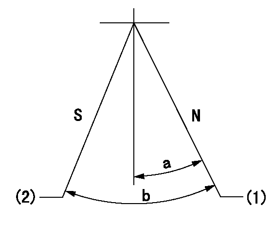
N:Pump normal
S:Stop the pump.
(1)Rack position = aa
(2)Rack position bb, pump speed cc
----------
aa=11.7mm bb=1+0.5mm cc=0r/min
----------
a=28deg+-5deg b=30deg+-3deg
----------
aa=11.7mm bb=1+0.5mm cc=0r/min
----------
a=28deg+-5deg b=30deg+-3deg
0000001501 Q ADJUSTMENT PIPING
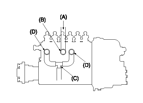
Tester fuel pipe A
Fuel inlet B
(C) Forked piping
(D) Overflow valve
Piping at standard injection quantity adjustment
1. Because the pump gallery is divided into two, be careful of the fuel piping at adjustment.
----------
----------
----------
----------
Timing setting

(1)Pump vertical direction
(2)Coupling's key groove position at No 1 cylinder's beginning of injection
(3)-
(4)-
----------
----------
a=(30deg)
----------
----------
a=(30deg)
Information:
Start By:a. remove oil pan 1. Remove bolts (1) that hold main bearing cap (2) in place. Remove main cap (2).2. Remove the bearing half from the cap.
If the crankshaft is turned in the wrong direction, the tab of the bearing will be pushed between the crankshaft and cylinder block. This can cause damage to either or both the crankshaft and cylinder block.
3. Remove the upper half of main bearings (3) as follows: a. Turn the crankshaft until tool (A) can be installed in the crankshaft journal. Install tool (A).b. Turn the crankshaft in the direction which will push the upper main bearing out, tab end first.c. Check the condition of the bearings. See "Guideline For Reusable Parts", "Main And Connecting Rod Bearings", Form No. SEBF8009 and SEBD0531. The following steps are for the installation of the crankshaft main bearings. Put clean engine oil on the main bearings for the assembly. Also, be sure the tabs on the back side of the main bearings fit in the grooves of the main bearings caps and cylinder block.
Ensure that the bearings are installed in the correct locations. Two different part numbers are used in the quantities of three and four. The part number having the quantity of four is to be installed on crankshaft main bearings 2, 3, 5 and 6. The part number having the quantity of three is to be installed on crankshaft bearing 1, 4 and 7.
4. Clean the surfaces in the cylinder block for the main bearings. Use tool (A), and install new upper halves of main bearings (bearings with the oil hole) in the cylinder block. Do not put oil on the back of the bearing.5. Clean the mating surface of the main bearing caps for the main bearings. Install the new lower halves of the main bearings in the main caps. Do not put oil on the back of the bearing.
Main bearing caps should be installed with the part number towards the right side. Caps are to be identified by stamped numbers 1 thru 7 located on the bottom unmachined surface.
6. Put main bearing caps (2) in position on the cylinder block. put clean engine oil or molylube on the bolt threads and the washer face; then install the bolts. Tighten the bolts on the side where the main bearing tabs are located to a torque of 95 5 N m (70 4 lb ft). Tighten the bolts on the opposite side to a torque of 95 5 N m (70 4 lb ft).7. Put a mark on each bolt head and the bearing caps. Turn the bolts that are opposite the main bearing tabs an additional 90° 5° turn. Then turn the bolts on the side where the main bearing tabs are located an additional 90° 5° turn.
Typical Example8. Check the end play of the crankshaft with a dial indicator and magnetic base. The end play must be 0.10 to 0.50 mm (.004 to .020 in). The
Have questions with 106691-0203?
Group cross 106691-0203 ZEXEL
Nissan-Diesel
Nissan-Diesel
106691-0203
9 400 617 749
1671396671
INJECTION-PUMP ASSEMBLY
PE6T
PE6T